
Clamp and hoisting device

Inactive Publication Date: 2014-03-06
NUDAWN METAL FAB
View PDF3 Cites 9 Cited by
  • Summary
  • Abstract
  • Description
  • Claims
  • Application Information

AI Technical Summary

Benefits of technology

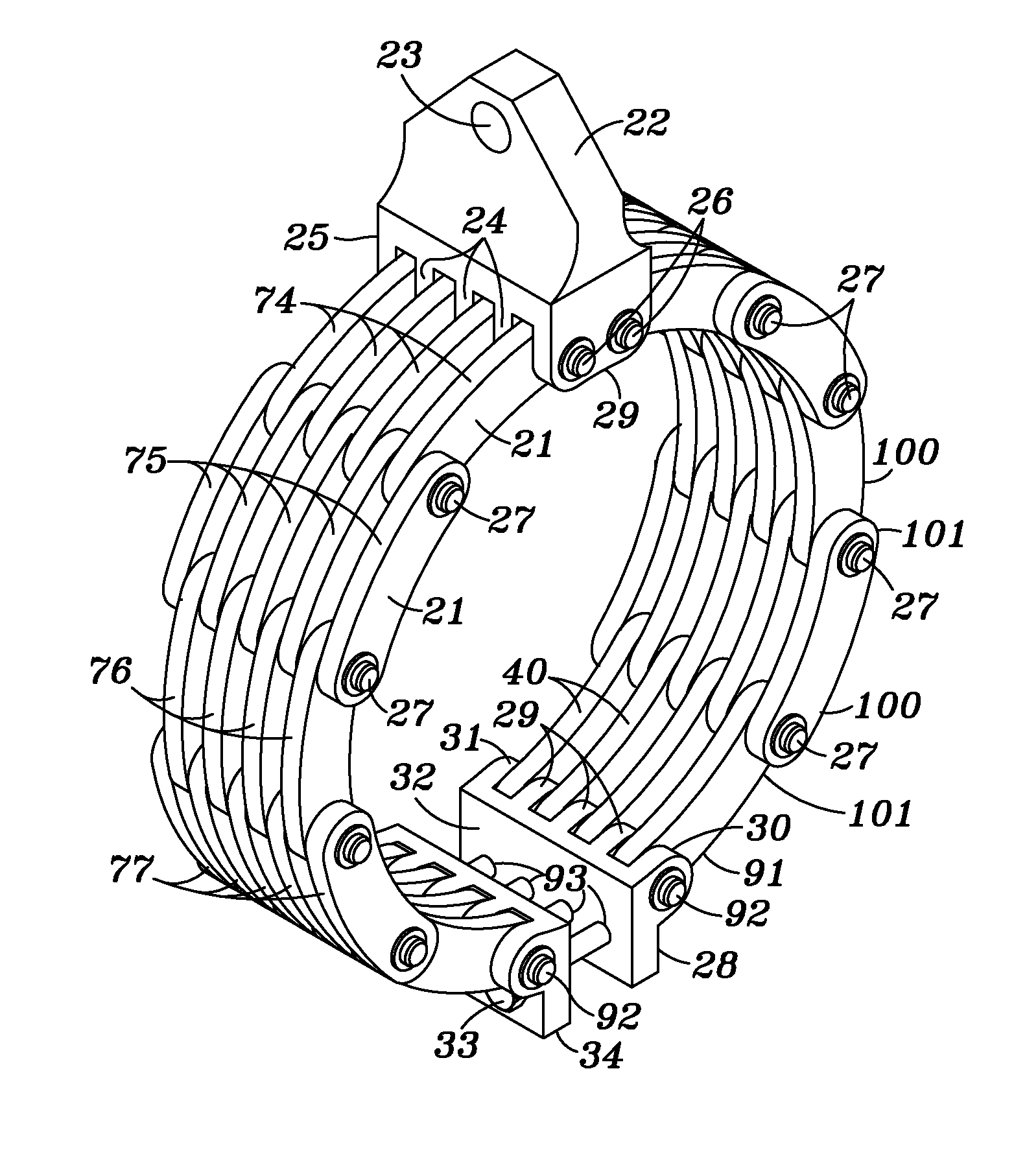
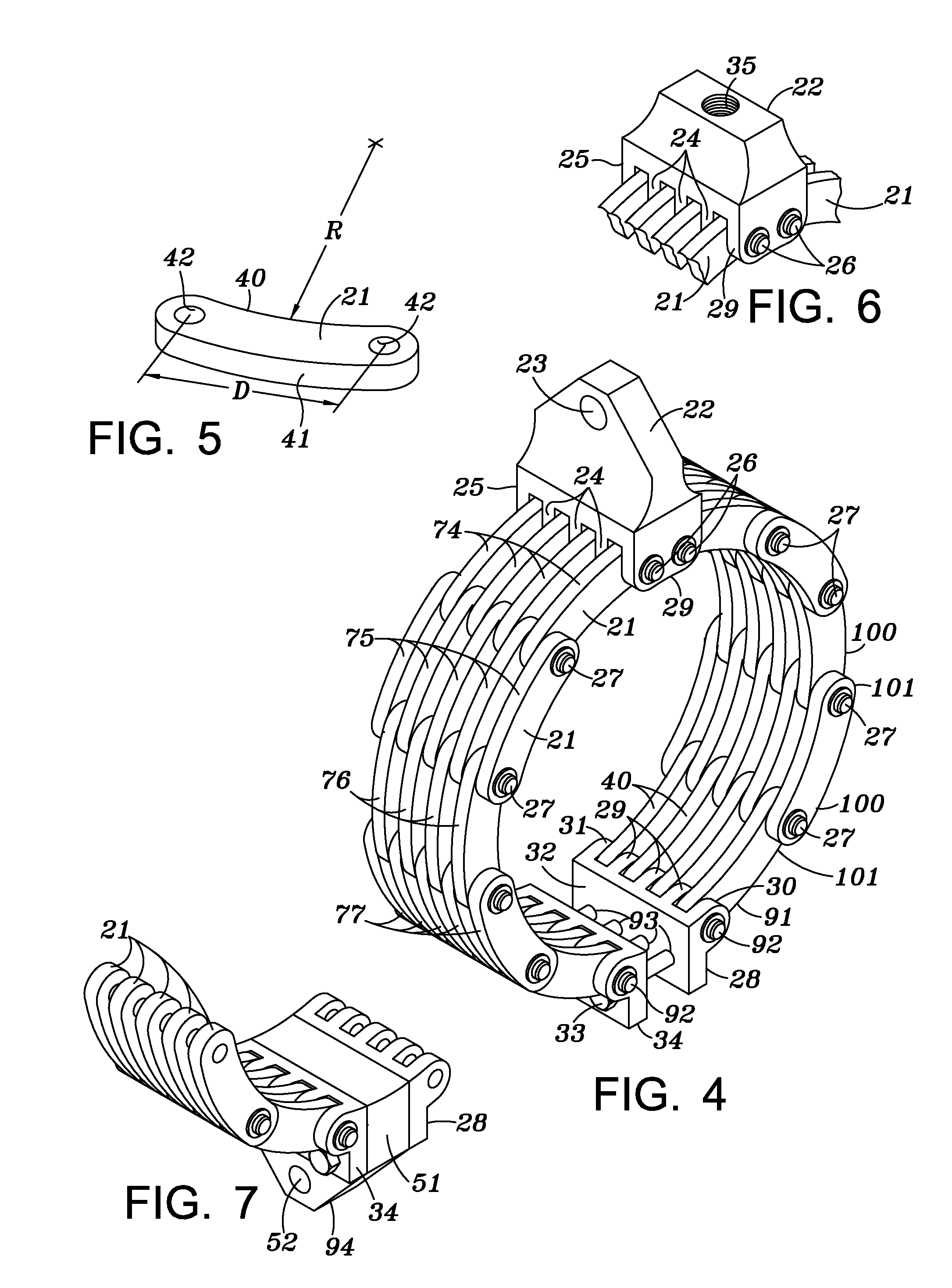
The invention is a clamp and hoisting device that can hold items in place on a tubular object, such as a riser pipe in offshore drilling. It is made of multiple curved links that create holding pressure points to prevent sliding. The clamp can also be used as a lifting device and to stop the buoyancy sleeve from shifting on riser. It can replace the need for straps and strapping, and can be used in high-stress environments. The clamp has a lift eye for easy lifting and can ensure protection against corrosion and harsh environments.

Problems solved by technology

A plurality of conduits extend along the riser pipe assembly and surround the clamp as shown in FIG. 3 making it difficult to access the clamps.

Method used


Image

  • Clamp and hoisting device
  • Clamp and hoisting device
  • Clamp and hoisting device

Examples


Embodiment Construction

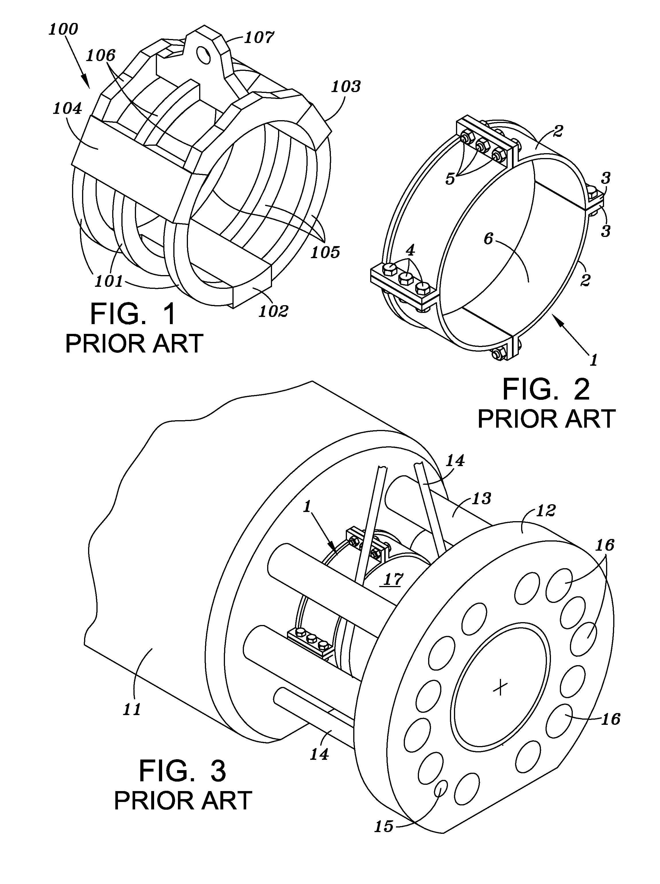
[0025]FIG. 1 illustrates a first prior art clamp 100. It includes a plurality of first lower ring members 101, second lower ring members 105, and third ring members 106. They are rigidly connected together by three solid blocks 102, 103, and 104. An attachment member 107 is fixed to the clamp and serves as an attachment member for a suitable hoisting device.

[0026]As described above, a second prior art clamp is shown in FIGS. 2 and 3. It includes a plurality of arcuate members 2 that include an inner surface 6 adapted to contact the outer surface of a tubular. The arcuate members include flanges 3 having apertures that are adapted to receive a plurality of bolts so that the arcuate members are rigidly attached to each other to form a clamp.

[0027]As shown in FIG. 3, the clamp 1 is secured to the tubular 17. A buoyancy sleeve 11 surrounds tubular 17 and clamp 1 prevents sleeve 11 from moving axially along the tubular. A plurality of conduits 13, 14 extend through sleeve 11 and are atta...


PUM


Abstract

A clamp and hoisting device serves the dual purpose of preventing a sleeve over a tubular or column like structure from sliding in an axial direction and also provides a connection point for a hoisting device. The device includes first and second arms composed of a plurality of arcuate links. Each arm is connected to an upper connector block and a lower connector block. The two arms are positioned over the tubular and the two lower connector blocks are secured to each other thereby forming a clamp. The upper connector block includes a connection point for attachment to a hoisting mechanism so that the clamp also serves as an attachment point for a hoisting mechanism.

Description

BACKGROUND OF INVENTION[0001]1. Field of the Invention[0002]This invention is directed to a device that can be used as a clamp to prevent items such as a buoyancy sleeve on a marine well rise pipe from sliding along the pipe and also can be used to lift the item by attachment to a suitable hoisting device. The device can be used as a clamp in any situation where it is desired to prevent axial movement of an outer member with respect to an inner member.[0003]2. Description of Related Art[0004]Marine well riser pipes typically are provided with a buoyancy sleeve that surrounds the riser pipe and is prevented from axial displacement by a pair of collars positioned on the pipe at the opposite ends of the sleeve. Current clamps as shown in FIGS. 1 and 2 of the drawings are composed of a plurality of arcuate portions having interior walls that engage the outer surface of the riser pipe. The sections are rigidly connected to each other by nuts and bolts passing through apertures formed in ...

Claims


Application Information

Patent Timeline
IPC IPC(8): B66C1/44
CPCB66C1/44
Inventor BIGGERT, CHARLES A.
Owner NUDAWN METAL FAB
Learn More