
Analog electronic timepiece

a technology of electronic timepieces and digital clocks, applied in instruments, horology, gearworks, etc., can solve the problems of inability to transmit rotation to the last gear, and inability to remove the influence of backlash in a manner

Active Publication Date: 2014-03-06
CASIO COMPUTER CO LTD
View PDF8 Cites 5 Cited by
  • Summary
  • Abstract
  • Description
  • Claims
  • Application Information

AI Technical Summary

Benefits of technology

The patent is for a timepiece that allows the pointer to easily move to a specific position when fast forwarding through a display. This allows for precise adjustment of the pointer to a specific position without fail.

Problems solved by technology

Therefore, there are cases where rotation cannot be transmitted to the last gear in the gear train mechanism and to the pointer connected to the last gear when the first gear in the gear train mechanism is rotated in a state having gaps in the meshing.
As a result, the position of the pointer predicted from the number of times the motor is driven and the position of the actual display of the pointer may not match and there may be a time lag until the reverse rotation of the pointer is started.
However, in analog electronic timepieces, because it takes time to move a pointer to the moving target position, there are cases where different fast forwarding movement is started while the pointer is moving fast forward.
In such cases, the influence of backlash cannot be removed appropriately and the position where the pointer points may be different from the predicted position in the conventional configuration.

Method used


Image

  • Analog electronic timepiece
  • Analog electronic timepiece
  • Analog electronic timepiece

Examples


Embodiment Construction

[0015]Hereinafter, an embodiment of the present invention will be described with reference to the drawings.

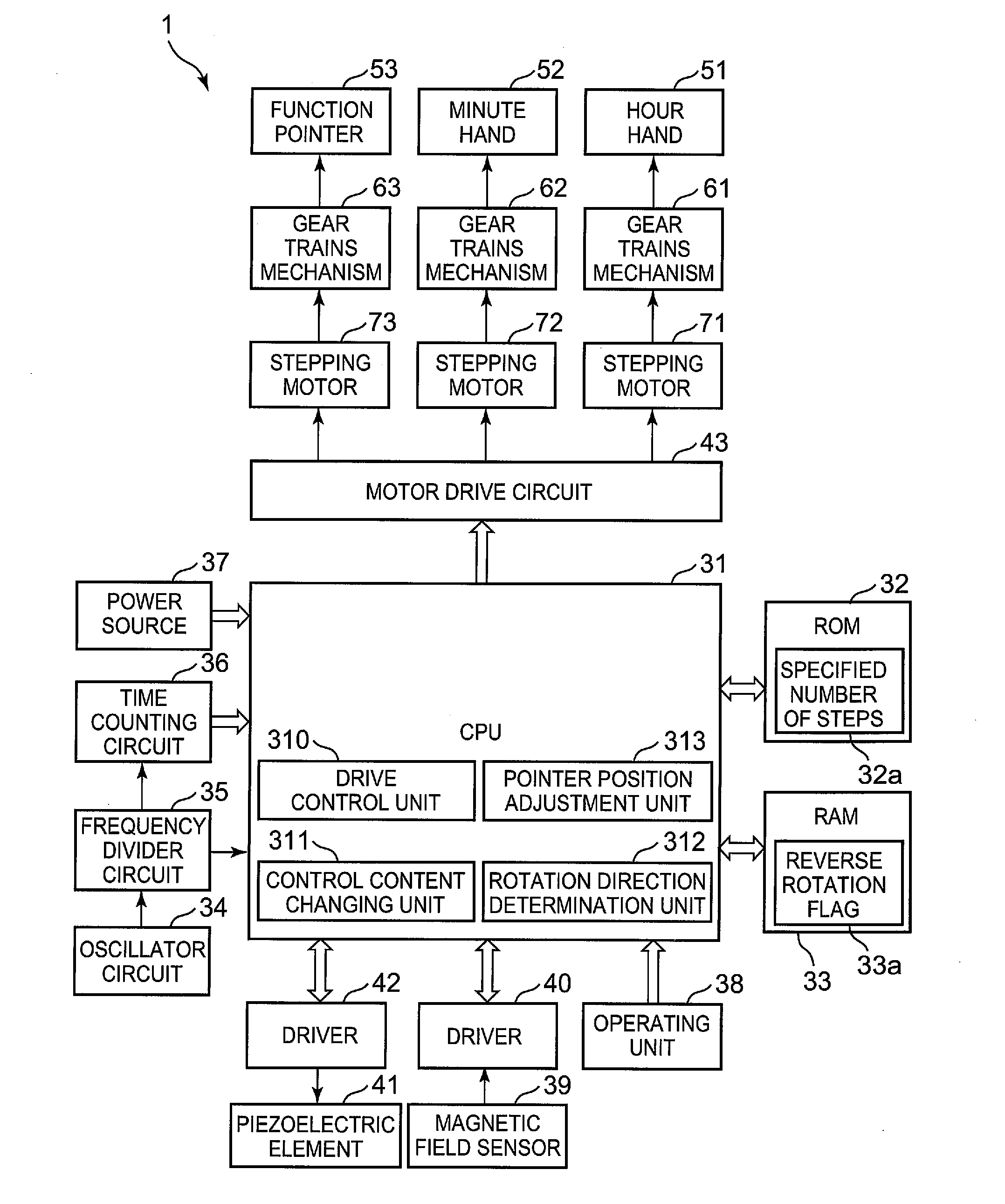
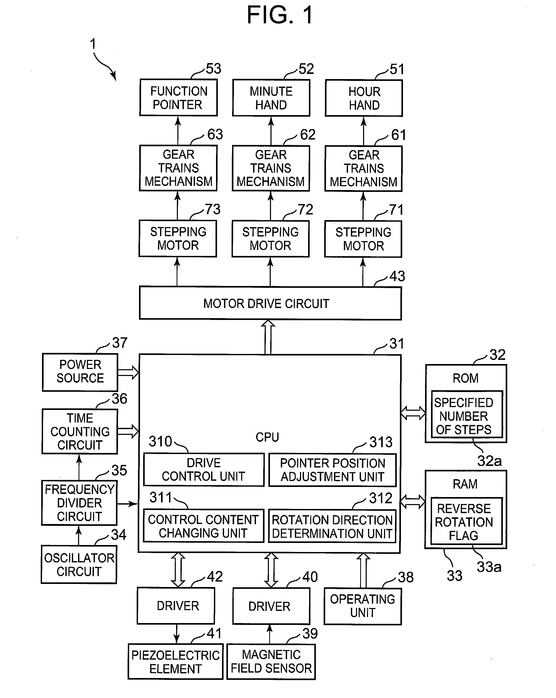
[0016]FIG. 1 is a block diagram showing an inner configuration of the analog electronic timepiece 1 according to the embodiment.

[0017]The analog electronic timepiece 1 can perform displaying according to various types of functions such as a world clock function, an alarm function, a timer function and a compass function, for example, in addition to a present time display function. The analog electronic timepiece 1 includes a CPU 31 (Central Processing Unit) (a drive control unit 310, a control content changing unit 311, a rotation direction determination unit 312, a pointer position adjustment unit 313), a ROM 32 (Read Only Memory), a RAM 33 (Random Access Memory), an oscillator circuit 34, a frequency divider circuit 35, a time counting circuit 36, a power source 37, an operating unit 38, a magnetic field sensor 39, a driver 40 for the magnetic filed sensor, a piezoelectric el...


PUM


Abstract

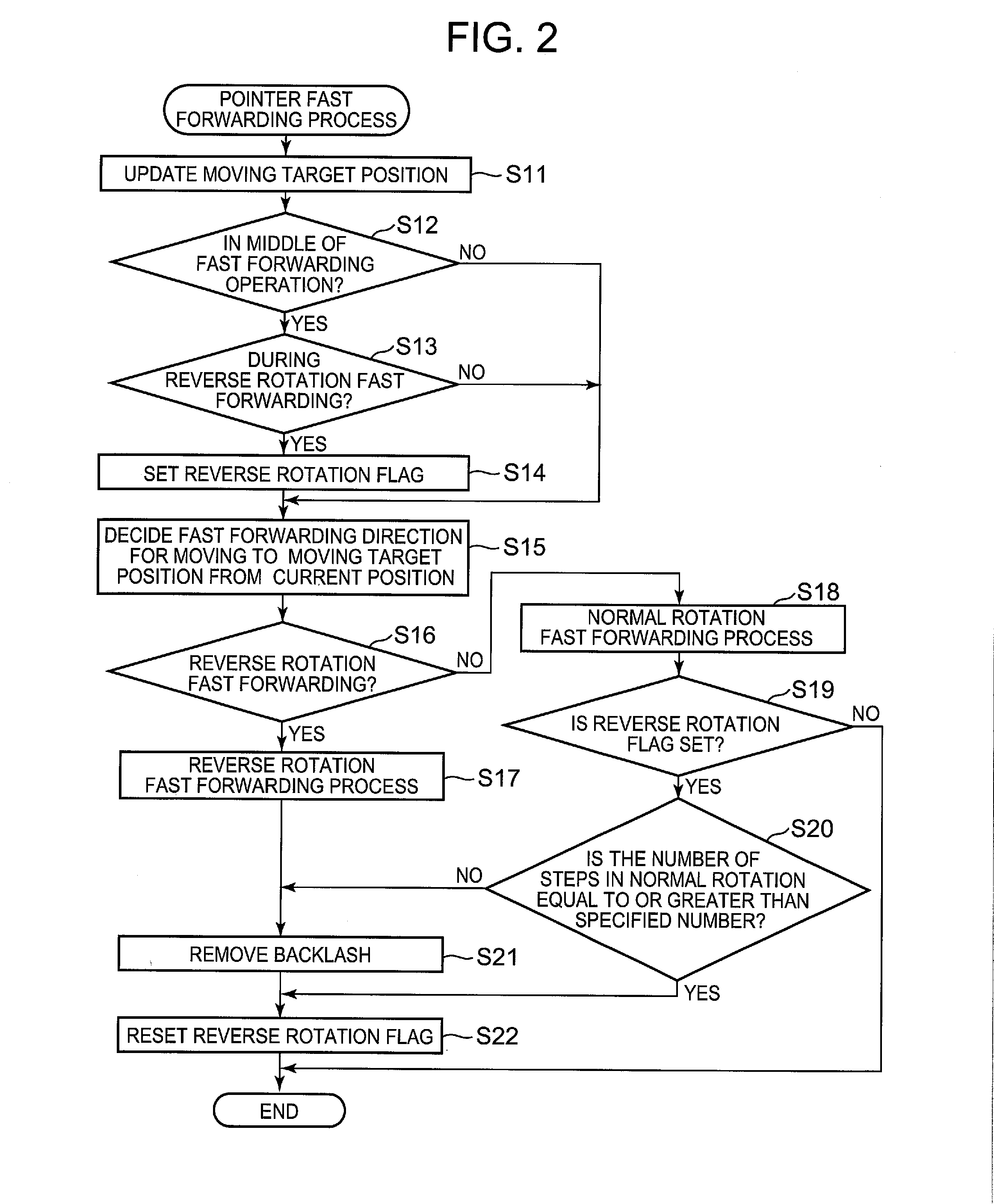
An analog electronic timepiece includes a stepping motor, a gear train mechanism having gears, a pointer, a drive control unit, a control content changing unit, and a pointer position adjustment unit. If an operational command to rotate the pointer to a different moving target position is obtained while an operational control for rotating the pointer to a certain moving target position is in progress, the control content changing unit terminates the control and changes a control content to an operational control according to the command. If the reverse rotation driving operation is being performed, the pointer position adjustment unit performs an adjustment operation for removing shifting between a predicted position of the printer and an actual position of the pointer which occurs because of rotational input from the stepping motor not being transmitted to the pointer due to gaps relating to the mesh of the gears.

Description

BACKGROUND OF THE INVENTION[0001]1. Field of the Invention[0002]The present invention relates to an analog electronic timepiece which displays the time with pointers.[0003]2. Description of Related Art[0004]Conventionally, analog electronic timepieces which display the time by the rotatable pointers pointing at predetermined directions (positions) are known. In such analog electronic timepieces, rotational operation of motors is transmitted to the gear train mechanisms wherein a plurality of gears are arranged and the pointers which rotate in conjunction with the last gears in the gear trains mechanisms move in the normal rotation direction and the reverse rotation direction.[0005]In the meshing of the gears which constitute a gear train mechanism, gaps (play spaces) which are called backlash are provided assuming that the gears can be modified slightly due to various causes such as temperature variation and aging. Therefore, there are cases where rotation cannot be transmitted to t...

Claims


Application Information

Patent Timeline
Patent Type & Authority Applications(United States)
IPC IPC(8): G04B19/02
CPCG04B19/02G04C3/146G04B13/027G04B13/00G04G5/00G04B35/00
Inventor HIROKAWA, JYUNICHIHISADA, SHIGEKITOKIWA, TERUHISA
Owner CASIO COMPUTER CO LTD
Learn More