Video encoding and decoding

a video and coding technology, applied in the field of digital signal processing, can solve the problems of reducing the coding efficiency, the solution does not consider the diversity of the predictors in the set, and the reduction so as to increase the compression ratio, reduce the loss, and increase the coding efficiency of the motion vector memory compression

Active Publication Date: 2014-03-06
CANON KK
View PDF18 Cites 26 Cited by
  • Summary
  • Abstract
  • Description
  • Claims
  • Application Information

AI Technical Summary

Benefits of technology

[0068]The invention can also be used to increase the coding efficiency of the motion vector memory compression. More precisely, in this case it is possible to reduce the loss (in terms of coding efficiency) generated by the block summarization of the motion vector memory compress

Problems solved by technology

This solution enables a significant reduction of the motion vector memory, with a coding efficiency penalty.
However, this solution does not consider the diversity of the predictors in the set for the block summarization in the MV memory compression.
Furthermore, this sol

Method used


Image

  • Video encoding and decoding
  • Video encoding and decoding
  • Video encoding and decoding

Examples


first embodiment

[0155]A first embodiment of the present invention will now be described.

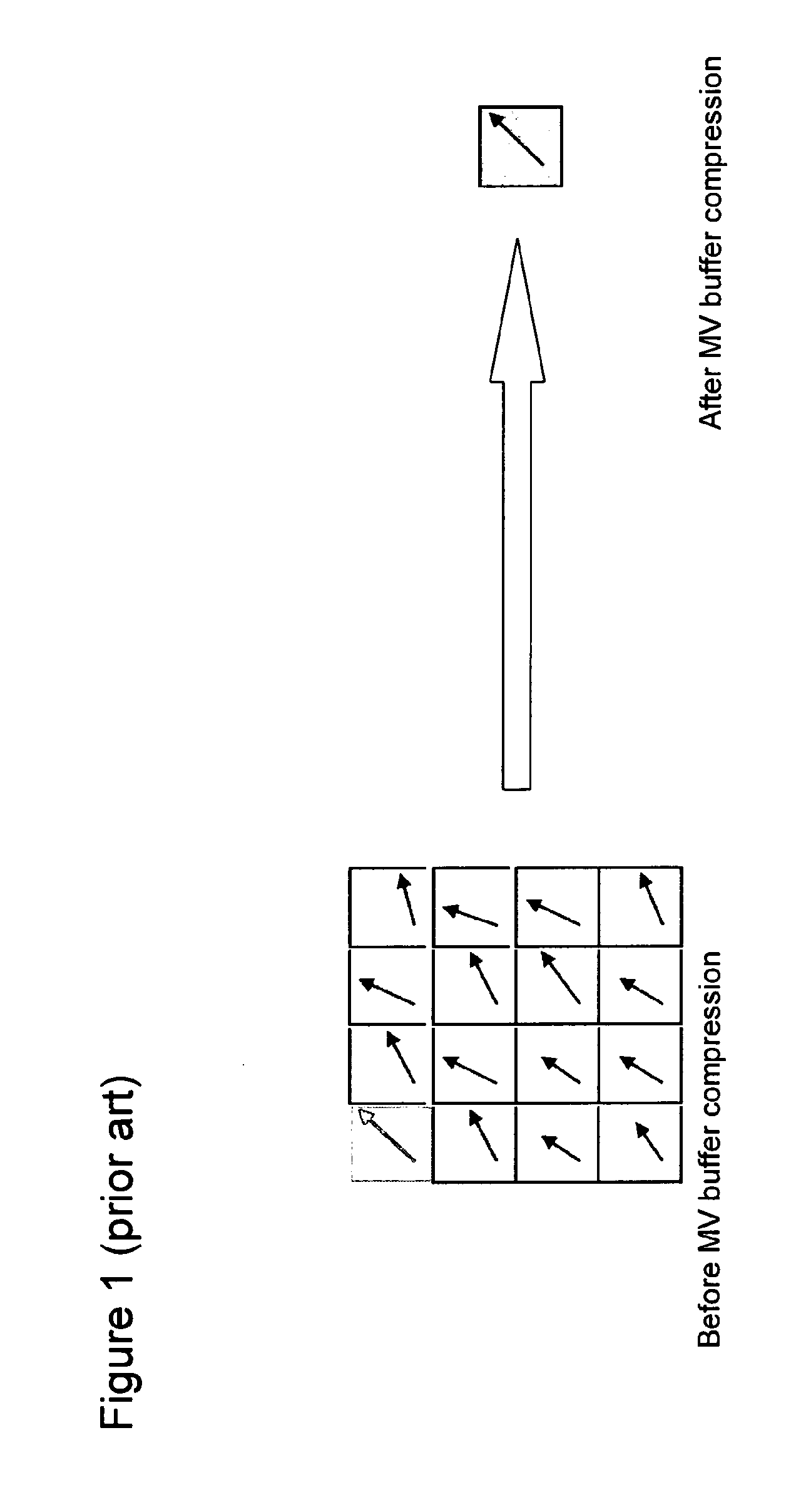
[0156]In the first embodiment, as in the proposals JCTVC-C257 and JCTVC-D072 mentioned in the introduction and shown in FIG. 1, one block position is used for the block summarization of a set of N×N motion vectors. The motion vector of the block corresponding to this one block position is stored as a representative motion vector for the entire N×N set. These prior proposals use exclusively the top left block position, as shown in FIG. 1. However, this way of summarization fails to take into account that the collocated motion vector predictor is used in a competitive scheme with other spatial predictors. As a result, although these prior proposals offer a significant reduction in the motion vector memory requirement (e.g. a factor of 16 reduction in the example of FIG. 1), they involve a penalty in terms of coding efficiency. For example, it is estimated that the use of 16 times reduction in the memory requiremen...

second embodiment

[0169]In the first embodiment no account is taken of the likelihood of selection of the spatial predictors at the different positions TP1-TP6 and LP1 to LP5. However, in the AMVP process, the search for the top predictor starts from the right-most position and moves to the left-most position, as already described with reference to FIG. 8. Thus, it is expected that the predictor at position TP6 will be selected more frequently than the predictor at position TP5, and so on from right to left in FIG. 12. The same is true for the left predictor, for which the search starts at the bottom position and moves upwards to the top position. Taking account of the relative frequencies of selection it may be preferable to adjust the average position for the top predictor to the right and the average position for the left predictor downwards. The average position for each predictor could be calculated as a weighted average of the potential positions, with the weights reflecting the relative select...

third embodiment

[0170]In the first and second embodiments described above, the encoder uses two spatial predictors (the top and left predictors). In the third embodiment, the encoder uses only one spatial predictor in the spatial predictors set. For example, if only the left predictor is used, the distance matrix of the left predictor given in FIG. 13A is used to find the best position. In that case, the position selected is block position number 6, the top right block. If only the top predictor is used, two block positions have the maximum value (block position number 11 and block position number 16). In that case, if AMVP is used as described with reference to FIG. 8, theoretically the predictors from the right side are more selected than the predictors from the left side (as explained, the predictors are selected from E to A in the HEVC derivation process). So, the algorithm can consider the use of the block numbered 11, because it should be the farthest block.


PUM


Abstract

A temporal motion vector predictor is includable, together with one or more spatial motion vector predictors, in a set of motion vector predictors for a block to encode of a current frame. A method of determining the temporal motion vector predictor comprises selecting as the temporal predictor one motion vector from among motion vectors in a reference block of a reference frame different from the current frame. The reference block is a block of the reference frame collocated with the block to encode or a block of the reference frame neighboring the collocated block. The selection is based on a diversity criterion for achieving diversity among the predictors of the set.
This can reduce the motion vector memory requirements with no or no significant additional coding efficiency penalty. Alternatively, even if the motion vector memory is not reduced in size, coding efficiency improvements can be achieved.

Description

FIELD OF THE INVENTION[0001]The invention relates to a method and device for encoding a sequence of digital images and a method and device for decoding a corresponding bitstream.[0002]The invention belongs to the field of digital signal processing, and in particular to the field of video compression using motion compensation to reduce spatial and temporal redundancies in video streams.DESCRIPTION OF THE PRIOR-ART[0003]Many video compression formats, for example H.263, H.264, MPEG-1, MPEG-2, MPEG-4, SVC, use block-based discrete cosine transform (DCT) and motion compensation to remove spatial and temporal redundancies. They can be referred to as predictive video formats. Each frame or image of the video signal is divided into slices which are encoded and can be decoded independently. A slice is typically a rectangular portion of the frame, or more generally, a portion of a frame or an entire frame. Further, each slice is divided into macroblocks (MBs), and each macroblock is further ...

Claims


Application Information

Patent Timeline
IPC IPC(8): H04N7/36H04N19/593
CPCH04N19/00684H04N19/105H04N19/139H04N19/176H04N19/43H04N19/46H04N19/52H04N19/593H04N19/513H04N19/61H04N19/107H04N19/503H04N19/463H04N19/51H04N19/157H04N19/521H04N19/44
Inventor LAROCHE, GUILLAUMEONNO, PATRICE
Owner CANON KK
Why Eureka
Try Eureka