Sensory input processing apparatus and methods

a technology of sensory input and processing apparatus, applied in the field of object recognition and identification, can solve the problems of increasing complexity, unable to develop appropriate spatial and temporal characteristics for extracting information from further inputs, and most existing approaches that fail to unify saccadic movements and temporal filtering with learning,

Active Publication Date: 2014-03-06
BRAIN CORP
View PDF8 Cites 88 Cited by
  • Summary
  • Abstract
  • Description
  • Claims
  • Application Information

AI Technical Summary

Benefits of technology

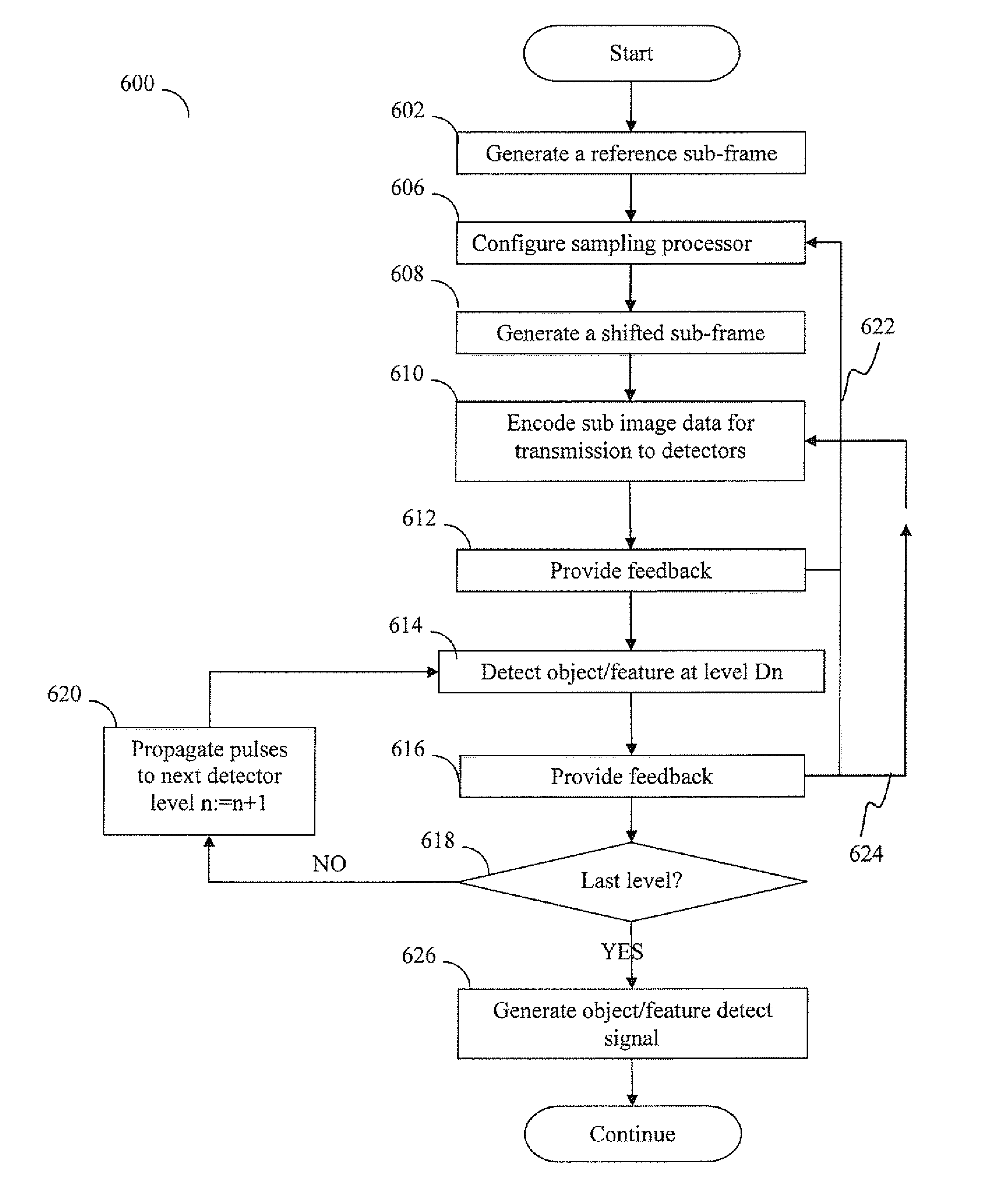
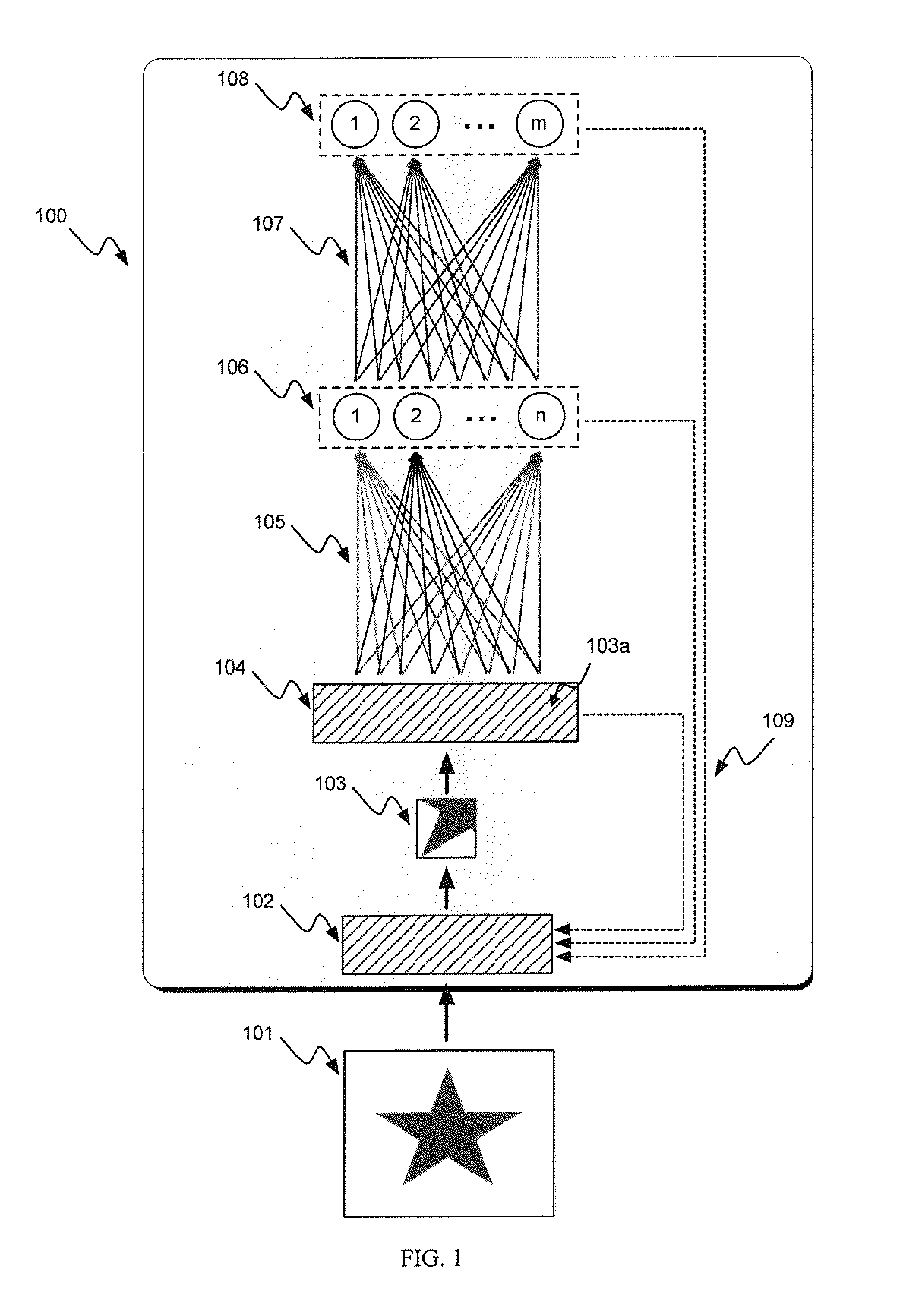
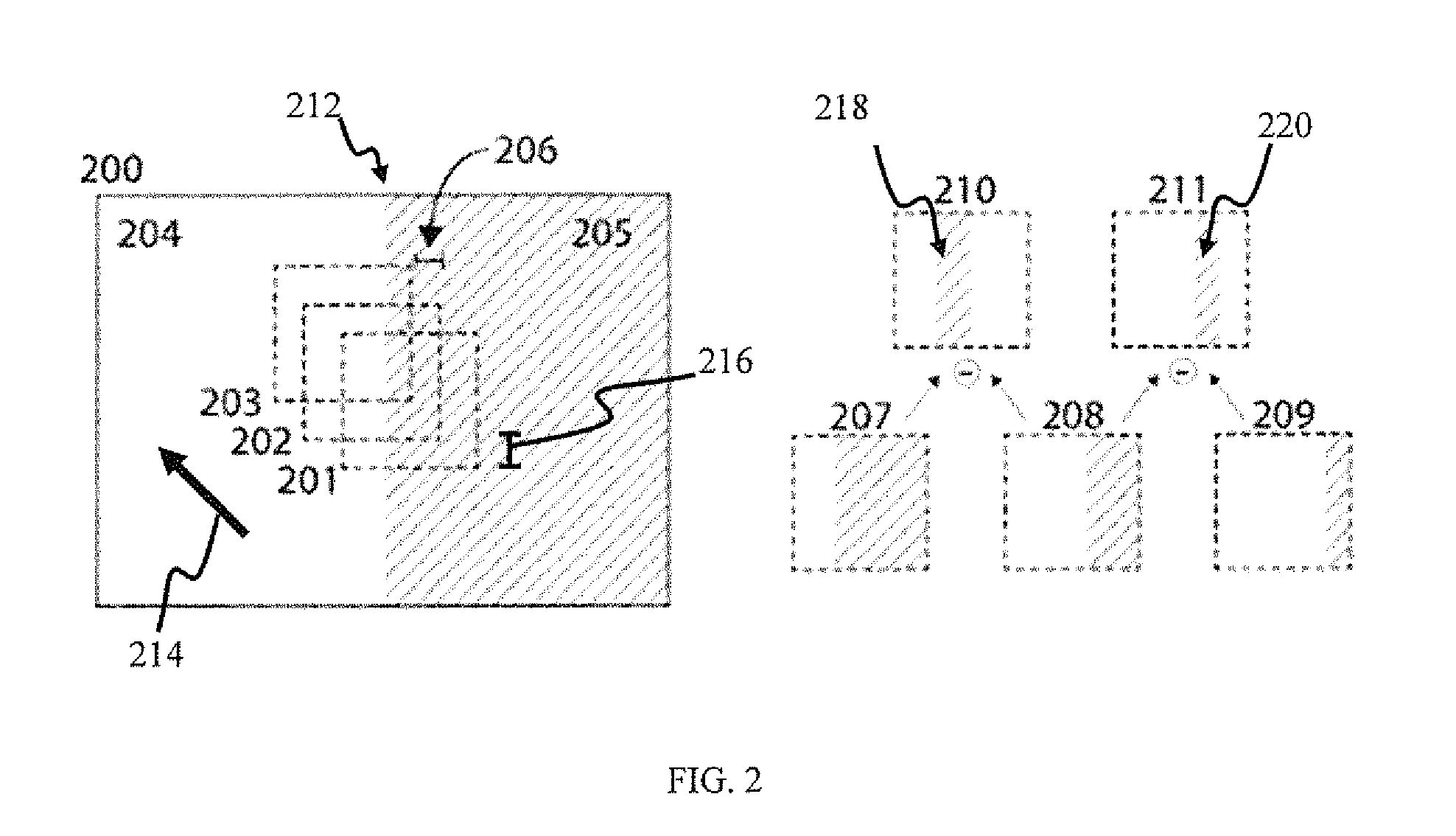
[0025]In one variant, at least one of the first sub-frame and the second sub-frame comprise at least a portion of the feature; the shift is configured to effect a detection of the feature, and information related to a spatial characteristic of the feature is encoded into a pattern of latencies of the group of pulses relative to one another based at least in part on the shifting.
[0026]In another variant, at least one of the plurality of the transmission channels is configured to effect a different time delay to at least one pulse of the group of pulses, the at least one pulse being transmitted via the least one of the plurality of transmission channels, and the detection of the feature comprises generating a detection signal based at least in part on a coincident arrival of at least two pulses at the decoder via the plurality of transmission channels.

Problems solved by technology

However, most existing approaches fail to unify saccadic movements and temporal filtering with learning, specifically spike-timing dependent plasticity.
Because the existing systems (such as Oster et. al., referred to supra) do not utilize the statistics of the inputs to evolve the system, the filters for spatial features do not develop appropriate spatial and temporal characteristics for extracting information from further inputs when the input statistics change over time.
Matched filter techniques disadvantageously require a multitude of filters, as they must be placed at multiple locations where the object can be present; each location requires filters tuned to different sizes or rotations of the feature or object, thereby further adding to complexity.

Method used


Image

  • Sensory input processing apparatus and methods
  • Sensory input processing apparatus and methods
  • Sensory input processing apparatus and methods

Examples


Embodiment Construction

[0036]Embodiments of the present invention will now be described in detail with reference to the drawings, which are provided as illustrative examples so as to enable those skilled in the art to practice the invention. Notably, the figures and examples below are not meant to limit the scope of the present invention to a single embodiment, but other embodiments are possible by way of interchange of or combination with some or all of the described or illustrated elements. Wherever convenient, the same reference numbers will be used throughout the drawings to refer to same or like parts.

[0037]Where certain elements of these embodiments can be partially or fully implemented using known components, only those portions of such known components that are necessary for an understanding of the present invention will be described, and detailed descriptions of other portions of such known components will be omitted so as not to obscure the invention.

[0038]In the present specification, an embodi...


PUM


Abstract

Sensory input processing apparatus and methods useful for adaptive encoding and decoding of features. In one embodiment, the apparatus receives an input frame having a representation of the object feature, generates a sequence of sub-frames that are displaced from one another (and correspond to different areas within the frame), and encodes the sub-frame sequence into groups of pulses. The patterns of pulses are directed via transmission channels to detection apparatus configured to generate an output pulse upon detecting a predetermined pattern within received groups of pulses that is associated with the feature. Upon detecting a particular pattern, the detection apparatus provides feedback to the displacement module in order to optimize sub-frame displacement for detecting the feature of interest. In another embodiment, the detections apparatus elevates its sensitivity (and/or channel characteristics) to that particular pulse pattern when processing subsequent pulse group inputs, thereby increasing the likelihood of feature detection.

Description

CROSS-REFERENCE TO RELATED APPLICATIONS[0001]This application is related to co-owned U.S. provisional patent application No. 61 / 318,191, filed Mar. 26, 2010 and entitled “APPARATUS AND METHOD FOR PULSE-CODE INVARIANT OBJECT RECOGNITION”, U.S. patent application Ser. No. 12 / 869,573, filed Aug. 26, 2010 and entitled “SYSTEMS AND METHODS FOR INVARIANT PULSE LATENCY CODING”, U.S. patent application Ser. No. 12 / 869,583, filed Aug. 26, 2010 and entitled “Invariant Pulse Latency Coding Systems and Methods”, U.S. patent application Ser. No. 13 / 117,048, filed May 26, 2011 and entitled “APPARATUS AND METHODS FOR POLYCHRONOUS ENCODING AND MULTIPLEXING IN NEURONAL PROSTHETIC DEVICES”, U.S. patent application Ser. No. 13 / 152,105 filed contemporaneously herewith on Jun. 2, 2011, and entitled “APPARATUS AND METHODS FOR TEMPORALLY PROXIMATE OBJECT RECOGNITION”, and U.S. patent application Ser. No. 13 / 152,084 filed contemporaneously herewith on Jun. 2, 2011 and entitled “APPARATUS AND METHODS FOR PU...

Claims


Application Information

Patent Timeline
Patent Type & Authority Applications(United States)
IPC IPC(8): G06K9/62
CPCG06K9/6232G06N3/049G06V10/454G06F18/213
Inventor PETRE, CSABASOKOL, SACH HANSENPIEKNIEWSKI, FILIP LUKASZSZATMARY, BOTONDIZHIKEVICH, EUGENE M.
Owner BRAIN CORP
Why Eureka
Try Eureka