
Method and process for an electric vehicle charging system to automatically engage the charging apparatus of an electric vehicle

a charging system and electric vehicle technology, applied in the field of electric vehicle charging system, can solve the problems of not being able to make it home that evening, traffic jam, weather not always perfect, etc., and achieve the effects of saving money, preventing waste, and increasing the cost of electric vehicle charging

Inactive Publication Date: 2014-03-06
CORNISH KEVIN TERRILL
View PDF2 Cites 133 Cited by
  • Summary
  • Abstract
  • Description
  • Claims
  • Application Information

AI Technical Summary

Benefits of technology

The patent text discusses the challenges of using traditional EV charging stations and the limitations of both inductive and conductive charging methods. The technical effects of the patent text include the development of an automated conductive charging system that overcomes the challenges of aligning the EV with the charging station and offers standards-based charging connectors. The system also addresses the issue of energy transfer loss and provides a more efficient and cost-effective solution for EV charging.

Problems solved by technology

Unfortunately, even in Southern California, the weather is not always perfect.
Traffic has been jammed, and so he / she is already late for a big meeting upon arriving at the public parking lot that offers EV charging which, unfortunately, is an additional five minute walk to the office building destination—but one has no choice due to the fact that EV charging infrastructure is not yet ubiquitous throughout the city.
Further, one has no choice but to re-charge the EV; otherwise, one won't be able to make it home that evening (i.e., range anxiety).

Method used


Image

  • Method and process for an electric vehicle charging system to automatically engage the charging apparatus of an electric vehicle
  • Method and process for an electric vehicle charging system to automatically engage the charging apparatus of an electric vehicle
  • Method and process for an electric vehicle charging system to automatically engage the charging apparatus of an electric vehicle

Examples


Embodiment Construction

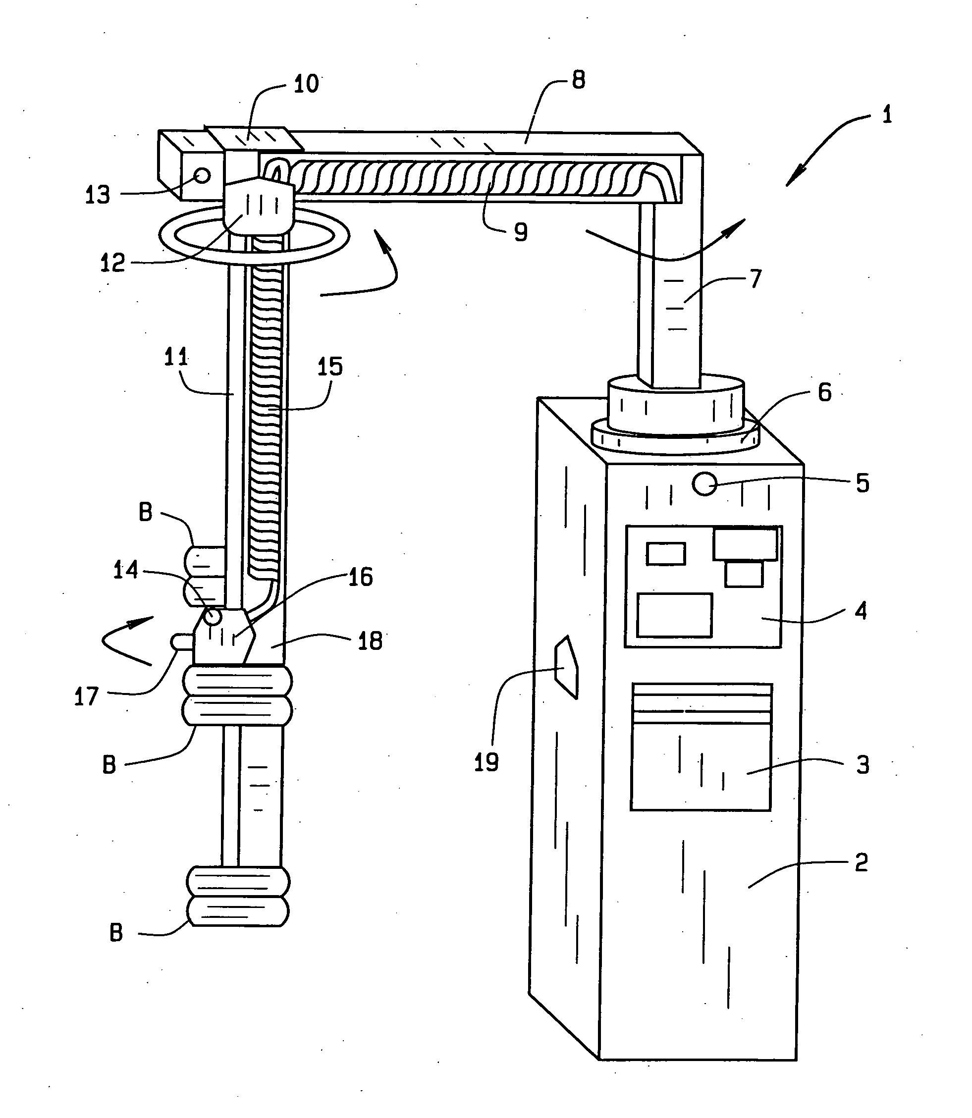
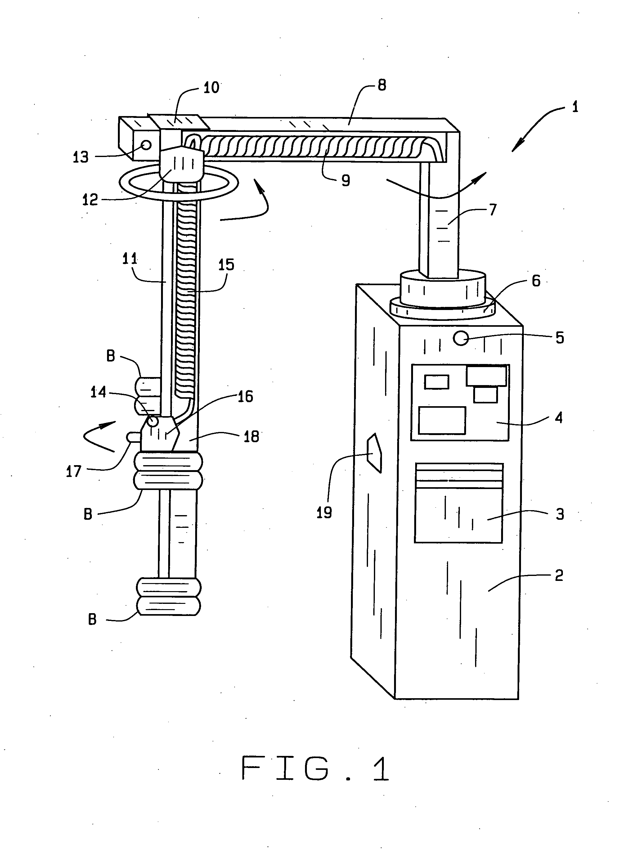
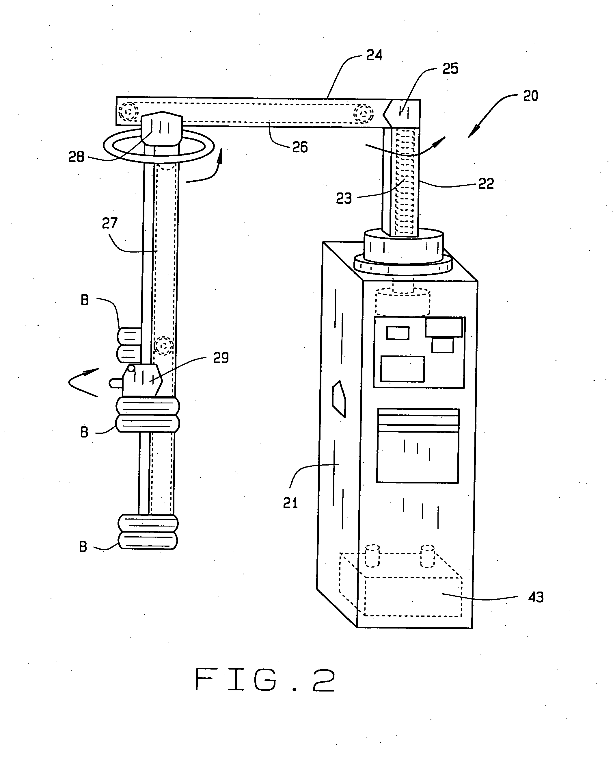
[0043]The new system of electric vehicle charging will automatically engage with an electric vehicle once the EV is within a defined range, space or field of reach of the charging station. By doing so, the EV will be engaged with the grid as an asset capable of providing energy (by way of discharge) in the event of a grid crisis, without the need for the EV owner to proactively connect his or her vehicle.

[0044]Further, by virtue of the automatic engagement of the charging station with the vehicle, EV owners will free themselves of exposure to the elements of inclement or unsettled weather.

[0045]The invention overcomes the limitations and weaknesses of the current art through the following:[0046]1. The Automated Vehicle Charging System (AVCS) will include motion sensors and / or cameras to detect the presence of a vehicle within its service territory. Upon detection of a vehicle, the AVCS will issue a request for information from the EV using its radio frequency based two way communica...


PUM


Abstract

An automated vehicle charging system, that may be done within a service type station, to provide for charging, recharging, or even discharging, of the batteries of an electric vehicle, and generally will include a dispenser, having a cabinet containing all of the instrumentation desired for furnishing the provision of current information relative to the charging of a vehicle, of otherwise, and will include boom means that are highly maneuverable, in order to bring the charging instrument into close proximity of the electrical receptacle of the vehicle being serviced, whether it be at a service type station, or at a curbside type of charging system. Robotics may be used within the structure of these electrical charging systems, to facilitate the charging of any vehicle, by the customer itself, even at a self service type of station.

Description

CROSS REFERENCE TO RELATED APPLICATION[0001]This continuation-in-part patent application claims priority to the non-provisional patent application having Ser. No. 13 / 385,620, filed on Feb. 27, 2012, which claims priority to the provisional patent application having Ser. No. 61 / 464,888, filed on Mar. 11, 2011.FIELD OF THE INVENTION[0002]The concept of this invention is to provide a system of electrical vehicle charging that will either automatically engage or electrically connect with an electric vehicle once it is within a defined range of the charger, and incorporates means for identification, charging of the vehicle, or discharging for credit, to facilitate and encourage the widespread usage of electric vehicles (EV) in society.BACKGROUND OF THE INVENTION[0003]Research has been conducted regarding electric vehicles dating back to the year 1832, when Scottish born Robert Anderson invented the first crude electric carriage powered by non-rechargeable primary cells, and related resea...

Claims


Application Information

Patent Timeline
Patent Type & Authority Applications(United States)
IPC IPC(8): G06Q20/14
CPCG06Q20/145Y02T90/14Y04S30/14B25J11/00B60L2250/10Y04S10/126B60L53/14B60L53/31B60L53/35B60L53/38B60L53/37B60L55/00B60L53/65B60L53/665B60L53/11B60L53/305Y02E60/00Y02T10/70Y02T10/7072Y02T90/12Y02T90/167Y02T90/16
Inventor CORNISH, KEVIN TERRILL
Owner CORNISH KEVIN TERRILL
Learn More