Apparatus for Monitoring Particles in an Aerosol

a technology for aerosols and apparatuses, applied in the direction of instruments, suspensions and porous material analysis, withdrawing sample devices, etc., can solve the problems of instruments suffering from particle loss, and achieve the effects of reducing the external dimensions or diameter of the apparatus, enhancing the reliability of operation, and simple mechanical structur

Active Publication Date: 2014-03-13
PEGASOR OY
View PDF2 Cites 11 Cited by
  • Summary
  • Abstract
  • Description
  • Claims
  • Application Information

AI Technical Summary

Benefits of technology

[0008]The present invention is based on the idea of providing an apparatus for monitoring particles of an aerosol by charging at least a fraction of the particles with an essentially particle free ionized gas fed into an ejector and removing ions not attached to the particles substantially downstream of the ejector with an ion trap formed as wire or rod. The ion trap wire may be straight or it may be bended to a curved configuration. The trap wire extends at least partly into the ejector. In one embodiment the trap wire is arranged to extend at least partly into the throat of the ejector. When the trap wire extends into the throat (preferably the diverging part of it), the ion trap utilizes the ejector structures and inner volume. As a result the total size of the measuring apparatus and the sample-gas residence time in the sensor can be reduced. The reduced residence time enables faster time response of the measurement apparatus.
[0010]The advantage of an ejector in a particle measurement apparatus which is based on the measurement of electrical charge carried by particles is that it allows a fast mixing of ions and particles. An ejector typically consists of three parts: inlet nozzle, throat and diverging outlet diffuser. The inventor has found that mixing of the motive fluid flow and the side flow in an ejector is so efficient that in practice the particles are charged by the ions carried by the motive fluid flow latest in the throat of the ejector. Thus the ion trap used to remove the excess ions from the flow may be assembled at least partly into the ejector and thus considerably shorten the flow path and minimize the size of the particle monitoring apparatus. This also minimizes particle losses into the particle measurement apparatus and enables faster time response of the apparatus. Preferably, especially in the case of cylindrically symmetric structure, the high-voltage electrode of the ion trap is rod-shaped, most preferably a wire, which does not essentially affect the flow pattern inside the particle measurement apparatus. The ejector surfaces, especially the inner surface of the diverging diffuser and in some cases also the inner surface of the throat, work as the ion collecting electrodes.
[0012]The present invention has the advantage that the ion trap wire provides a simple mechanical structure for the ion trap. The simple mechanical structure enhances the reliable operation such that the apparatus for monitoring particles or the particle sensor may be operated long time periods without need for maintenance. The ion trap arrangement in which the trap conductor extends inside the measurement housing from the inlet chamber to the ion trapping chamber and ejector provides also a compact structure and decreases the external dimensions or diameter of the apparatus. The trap wire may also be formed into a configuration which enables decreasing the dimensions of the ion trapping housing and thus the external dimensions or the length of the apparatus. The trap wire may also be formed into a configuration which enables use of moderate ion trapping voltages.

Problems solved by technology

The publication fails, however, to describe the advantages which are achievable by using an ejector and thus the instrument may suffer from particle losses.

Method used


Image

  • Apparatus for Monitoring Particles in an Aerosol
  • Apparatus for Monitoring Particles in an Aerosol
  • Apparatus for Monitoring Particles in an Aerosol

Examples


Embodiment Construction

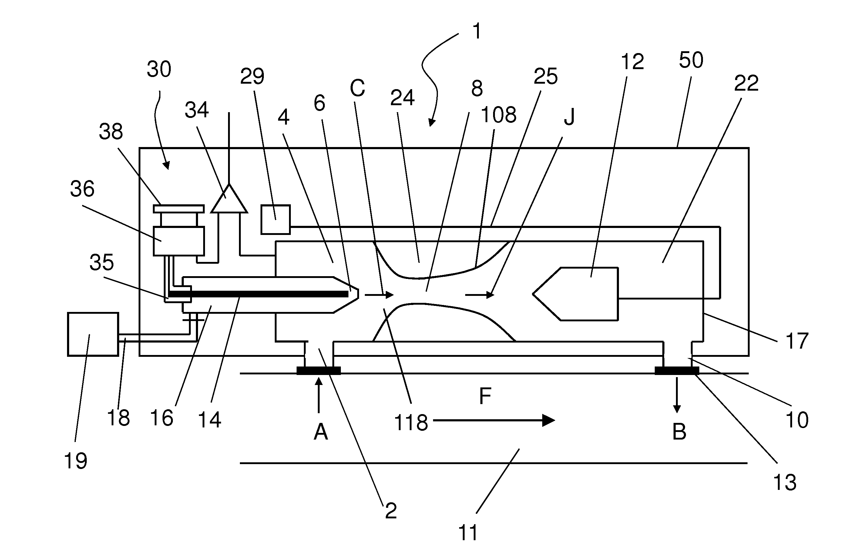
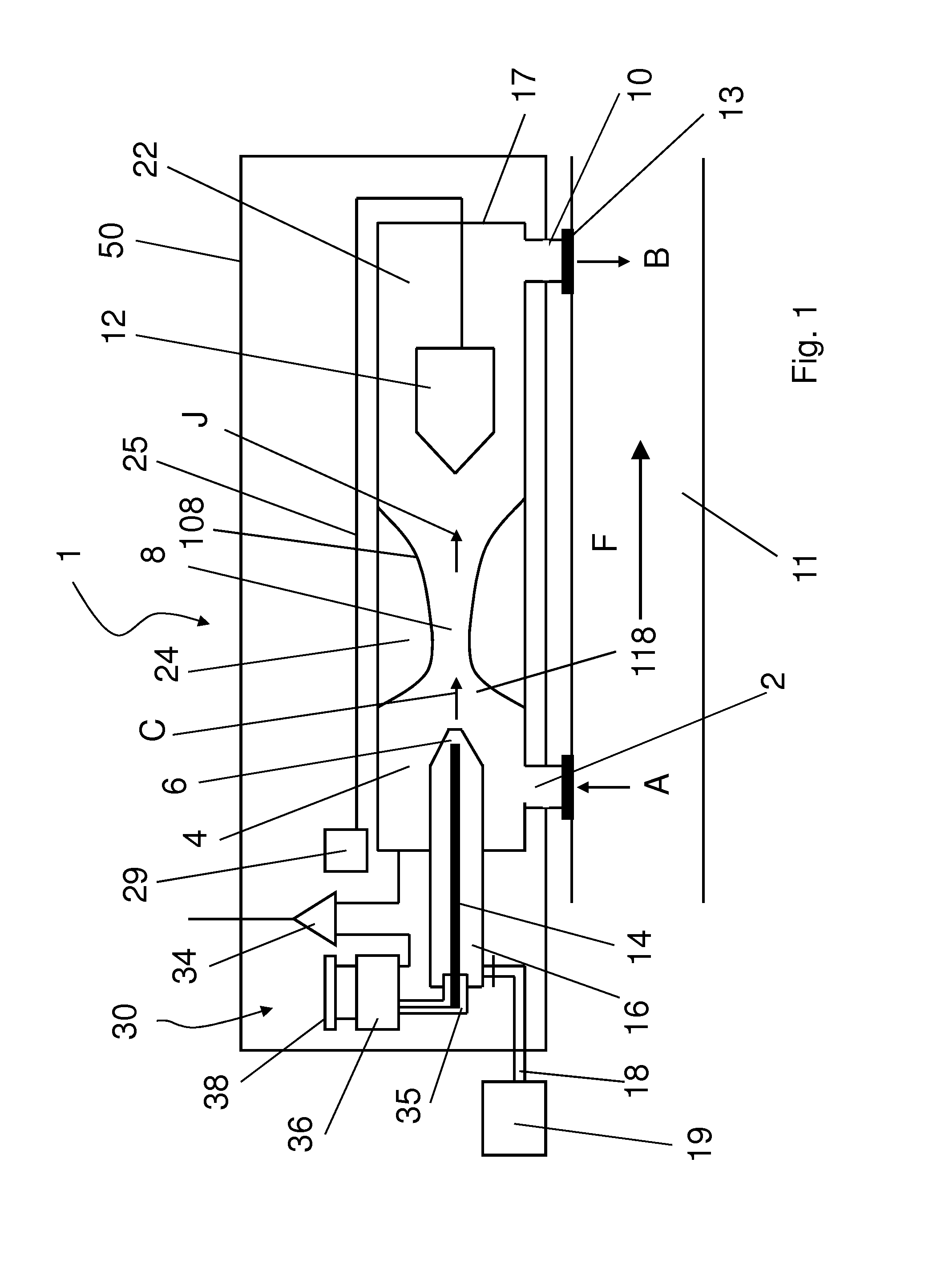
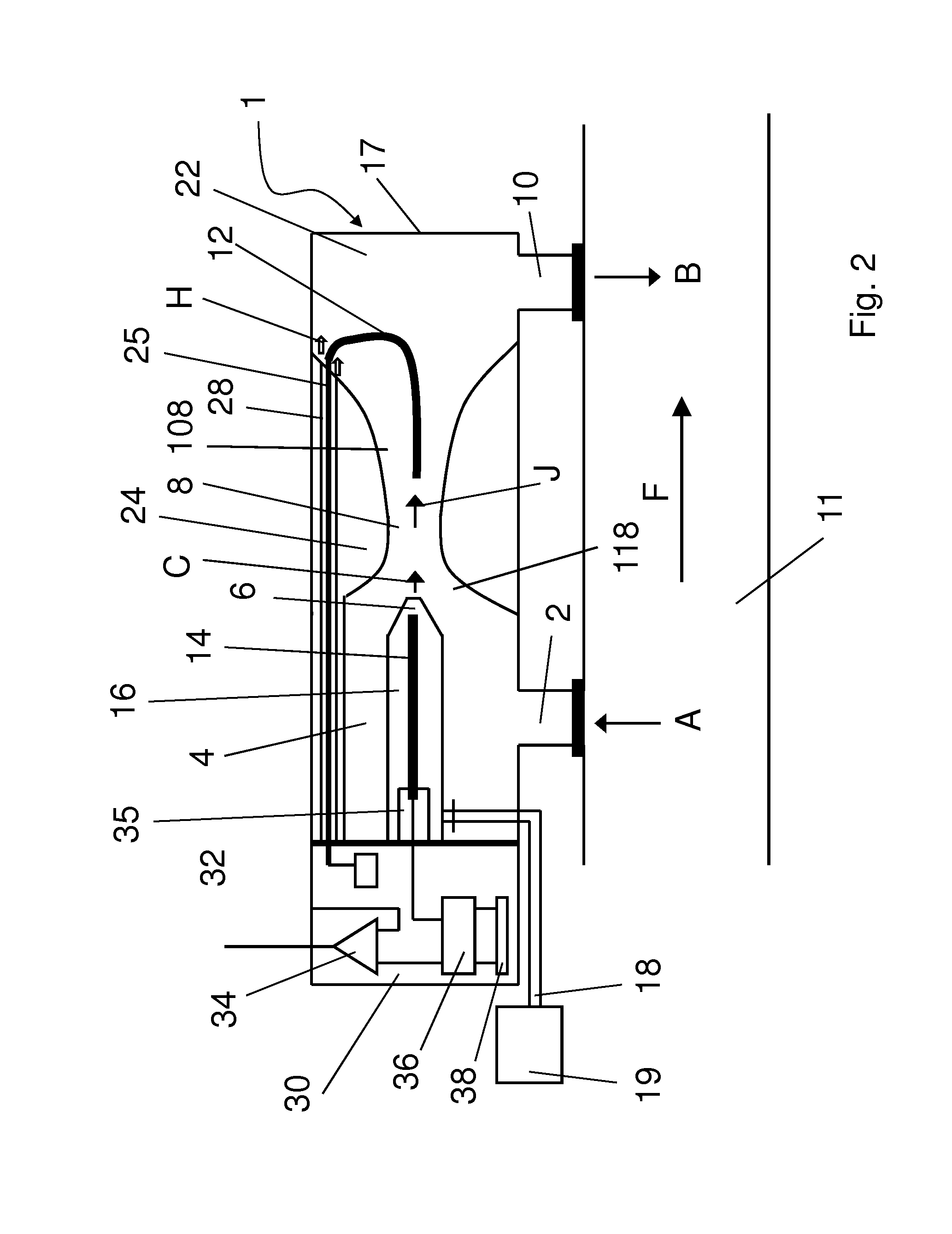
[0017]The FIG. 1 shows one embodiment of a prior art apparatus for monitoring particles. The apparatus comprises an outer body 50 inside which is provided a measurement housing 17 and at least part of the electrical components and conductors 30 of the apparatus. As seen in FIG. 1 the electrical components and connectors 30 are arranged substantially outside of the measurement housing 17, thus between the outer body 50 and the measurement housing 17.

[0018]The measurement housing 17 provides space in which the particles monitoring of the aerosol is conducted. A sample aerosol flow A is guided from a channel, duct or a space comprising aerosol inside the measurement housing 17 for monitoring or measuring particles in the aerosol. The apparatus 1 is connected to an aerosol duct 11 in side which is an aerosol flow F. Thus the apparatus 1 is arranged to monitor fine particles or particles in the aerosol flow F. The aerosol duct may be exhaust duct of a combustion engine or the like. Alter...


PUM

PropertyMeasurementUnit
electric fieldaaaaaaaaaa
magnetic fieldaaaaaaaaaa
collection voltageaaaaaaaaaa

Abstract

The present invention relates to an apparatus (1) for monitoring particles in a channel (11) or a space comprising aerosol and to an ion trap arrangement in the apparatus. The apparatus (1) comprises an ejector (24), gas supply (6, 16, 18, 19) arranged to feed an essentially particle free ionized gas flow (C) to the ejector (24), a sample-inlet arrangement (2) arranged to provide a sample aerosol flow (A) from the channel (11) into the ejector (24) by means of suction provided by the gas supply (6, 16, 18, 19) and the ejector (24) for charging at least a fraction of the particles of the sample aerosol flow (A), and an ion trap (12) extending at least partly into ejector (24) for removing ions not attached to the particles. According to the invention the ion trap (12) is a provided as a metal trap wire.

Description

FIELD OF THE INVENTION [0001]The present invention relates to an apparatus for monitoring particles and especially to an apparatus as defined in the preamble of independent claim 1.BACKGROUND OF THE INVENTION[0002]Fine particles having diameter are formed in many industrial processes and combustion processes. For various reasons these fine particles are measured. The fine particle measurements may be conducted because of their potential health effects and also for monitoring operation of industrial processes and combustion processes, such as operation of combustion engines, especially diesel engines. Another reason for monitoring fine particles is the increasing use and production of nanosized particles in industrial processes. The above reasons there is need for reliable fine particle measurement equipments and methods.[0003]One prior art method and apparatus for measuring fine particles is described in document WO2009109688 A1. In this prior art method clean, essentially particle ...

Claims


Application Information

Patent Timeline
Patent Type & Authority Applications(United States)
IPC IPC(8): G01N27/62
CPCG01N27/62G01N1/2252G01N15/0656G01N1/22G01N1/24G01N15/06G01N15/10
Inventor JANKA, KAUKO
Owner PEGASOR OY
Why Eureka
Try Eureka