Method and apparatus for a product cooler

a technology for product coolers and coolers, applied in the field of product dispensers, can solve the problems of requiring a still larger ice-box, unable to easily fit the “bulk” version into the cooler, and unable to allow spillage, condensate, drips, etc., and achieve the effect of easing the removal of the product packag

Inactive Publication Date: 2014-03-13
GUERRERO JR GILBERT F +1
View PDF5 Cites 5 Cited by
  • Summary
  • Abstract
  • Description
  • Claims
  • Application Information

AI Technical Summary

Benefits of technology

[0018]In an extension of the second embodiment, the container system further includes a take-up hoop disposed within the chamber to elevate loose packaging, ther...

Problems solved by technology

A glued joint does not allow any spills, condensate, or drips to contact the interior foam.
While single-serve product units fit into the product coolers without issue, “bulk” versions do not easily fit into coolers.
In fact, problems arise when a product unit having a dispense valve requires cooling, because on gravity fed products, a dispense valve is disposed at a lowest end of the product unit.
Still further, produc...

Method used


Image

  • Method and apparatus for a product cooler
  • Method and apparatus for a product cooler
  • Method and apparatus for a product cooler

Examples


first embodiment

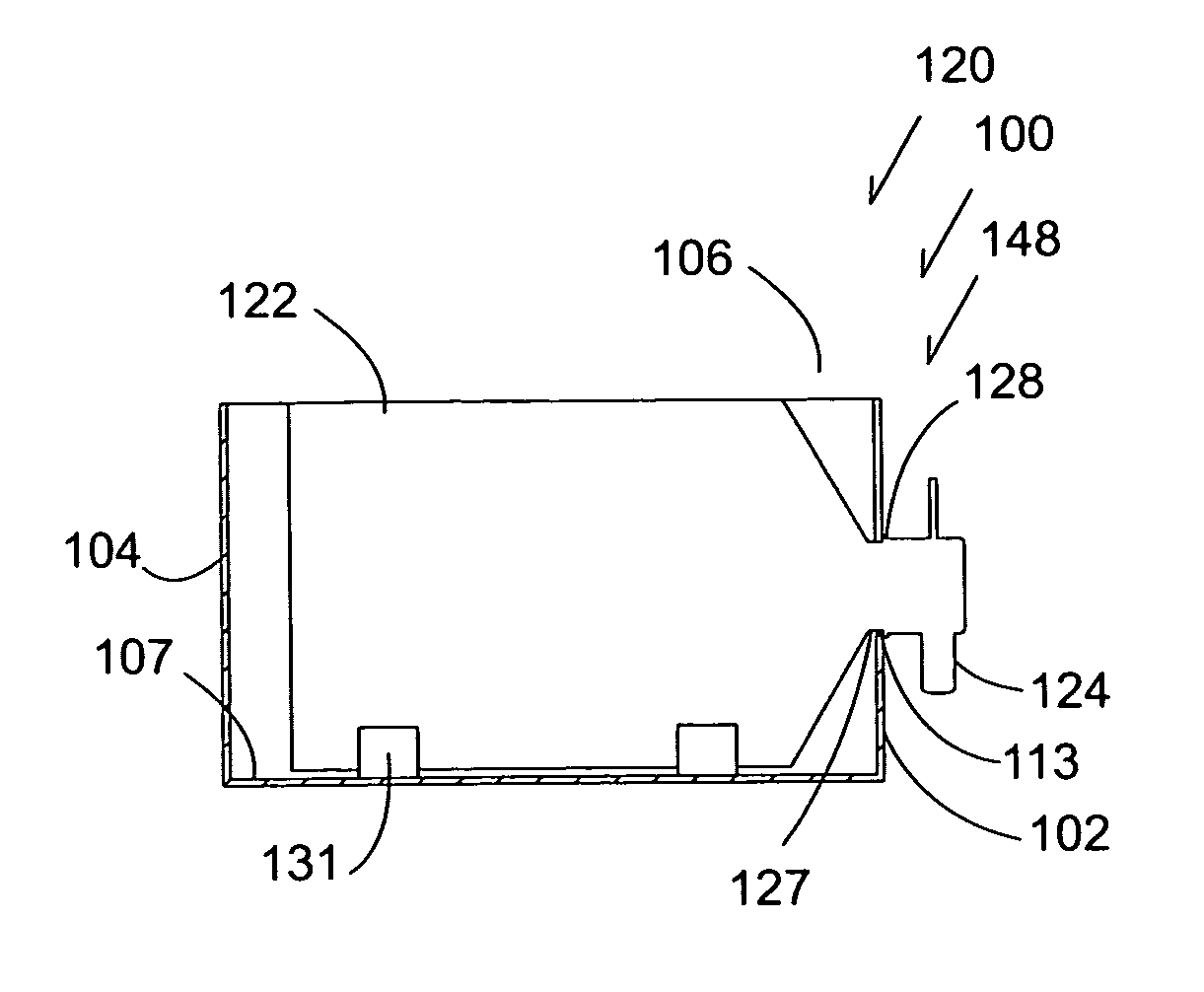
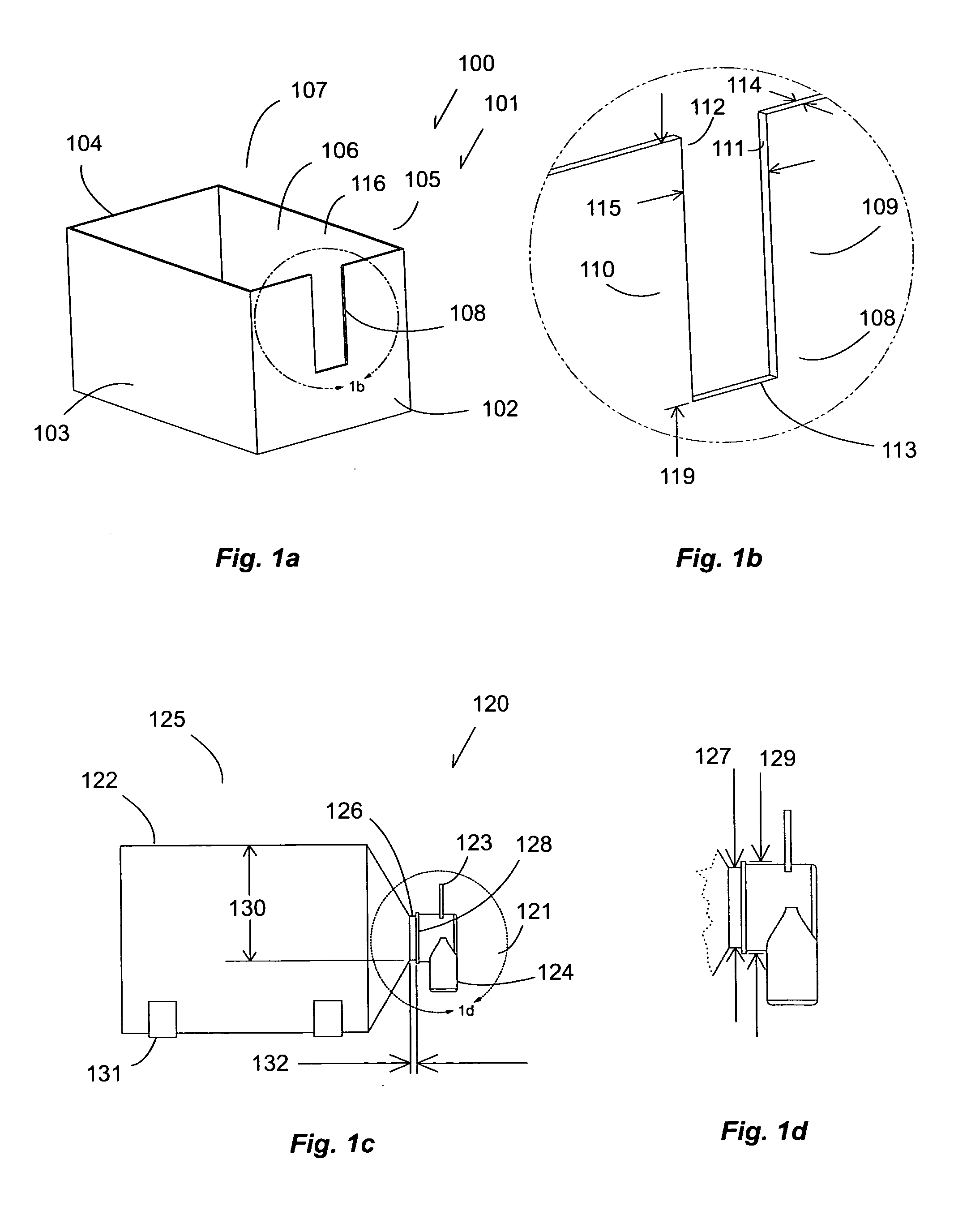
[0052]In this particular example, the first wall 102 includes a slot 108 extending from the inlet 116. The slot 108 includes a first engagement face 111 disposed on a first side 109, a second engagement face 112 disposed on a second side 110, and a stop 113 disposed between the first engagement face 111 and the second engagement face 112. In this particular example, the first wall 102 is of a thickness 114, and the slot 108 is of a width 115. In this first embodiment, the stop 113 is disposed a distance 119 from the inlet 116 of the chamber 106. The distance 119 represents a distance from a top edge of a product unit to a lowermost portion of a minor diameter of the product unit to ensure that a product vessel of the product unit is disposed within the chamber 106 when the minor diameter engages the stop 113.

[0053]In this first embodiment, the product unit 120 is a commonly available pressurized dispensing container, and is often utilized to dispense beer while sitting on a shelf in...

second embodiment

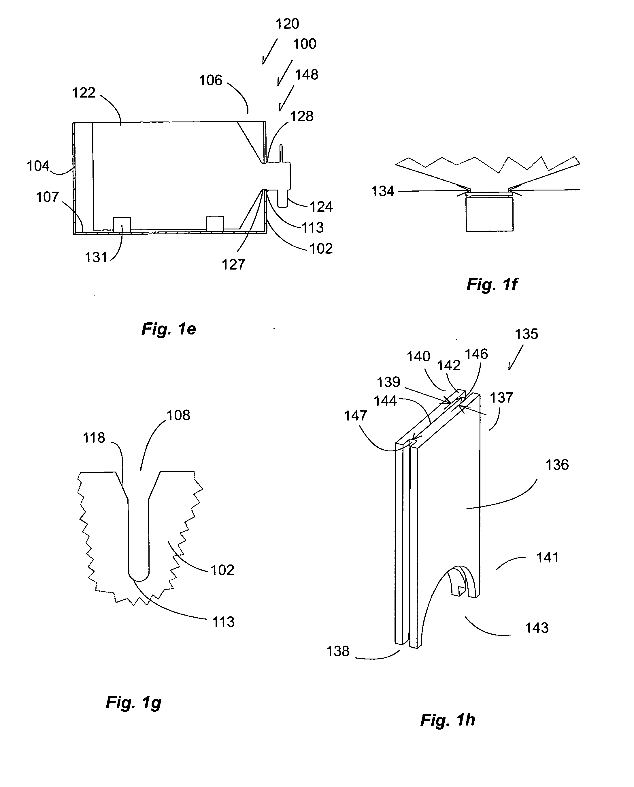
[0089]In an extension of the second embodiment, a container system 210 further includes a take-up hoop 236 for removing slack from the product vessel 222. The take-up hoop 236 includes a mounting face 237, and a cantilevered face 238 having a restraint slit 239. The cantilevered face 238, preferably is parallel to the floor of the chamber 206, and is disposed at an elevation near to the inlet 216 to lift any loose ends of the product vessel 222. The restraint slit 239 is of a width slightly larger than the thickness of four plys of the product vessel 222 material, such that the material that has been inserted through the restraint slit 239 does not easily come out of the restraint slit 239.

[0090]In this specific example, take-up hoop 236 includes mounting holes for securing the mounting face 237 to an inner wall of the chamber 206 with fasteners. On assembly, the mounting face 237 is positioned such that the cantilevered face 238 is disposed substantially parallel to the floor and a...

third embodiment

[0102]While this third embodiment has been shown with a product unit 320 that may be broken down to be sanitized, one of ordinary skill in the art will recognize that it is possible to permanently join a dispensing valve to the product vessel if the product vessel is formed from polyvinyl chloride or acetyl butyl styrene. In the case of a permanent joint, the sanitizing process would require the passage of detergents through the product path to sanitize the internal components.

[0103]While this third embodiment has been shown in a simplest form, one of ordinary skill in the art will recognize that all of the extensions of the first and second embodiments may be utilized in the third embodiment, and, therefore, should be considered to be part of the third embodiment.


PUM


Abstract

A container system allows a user to register a bulk product unit at a predetermined elevation by engaging a stop disposed at a deepest point of an engagement slot. The engagement slot is disposed in a wall of a container containing a chamber having an inlet for receiving a product vessel. The neck of the product unit may be lowered into the slot, thereby moving the product vessel through the inlet of the chamber, and positioning the dispensing valve outside of the container. The first embodiment further comprises a retrofit system for adapting an existing product cooler to contain a saddle to support the neck of a bulk product unit. In a second embodiment, the container system is designed to receive and dispense gravity fed flexible packages, such as bulk wine. In a third embodiment, the container system comprises a product unit that is refillable, sealable, and separable for cleansing.

Description

BACKGROUND OF THE INVENTION[0001]1. Field of the Invention[0002]The present invention relates to dispensing product at a remote location, and, more particularly, but not by way of limitation, to methods and an apparatus for creating a container system capable of delivering a variety of products from a variety of product containers disposed within a chamber of the container system.[0003]2. Description of the Related Art[0004]Ice chest manufacturers provide coolers for storage of most single-serve products, such as cans, bottles, ice, and the like. Product coolers are available in virtually any size, shape or color, and the thermal efficiencies of the product coolers are always getting better, however, a same basic shape is almost always utilized. Namely, a rectangular shape having a cavity or chamber for storing product units is utilized. An exterior layer is often formed from two separate pieces that are joined together to protect an interior foam. A glued joint does not allow any s...

Claims


Application Information

Patent Timeline
IPC IPC(8): B65D6/40
CPCB65D77/065
Inventor GUERRERO, JR., GILBERT F.VIRA, JOHN
Owner GUERRERO JR GILBERT F
Why Eureka
Try Eureka