Vehicular lamp

a technology of vehicle lamps and lampshades, which is applied in the field of vehicle lamps, can solve the problems that the generation of irregular light emission in the light guide body cannot be effectively suppressed, and the appearance of the lamp is deteriorated, so as to achieve the effect of enhancing the light utilization efficiency of light emitted and effectively suppressing the generation of irregular light emission

Inactive Publication Date: 2014-03-13
KOITO MFG CO LTD
View PDF11 Cites 32 Cited by
  • Summary
  • Abstract
  • Description
  • Claims
  • Application Information

AI Technical Summary

Benefits of technology

[0012]Exemplary embodiments of the invention provide a vehicular lamp including a light guide body which can suppress the generation of irregular light emission effectively while enhancing the light utilization efficiency of light emitted from a light source.

Problems solved by technology

Because of this, when observing the front surface of the light guide body from the front thereof, a dark portion is generated between the first entrance portion and the reflecting portion, which generates irregularity in light emission, and therefore, a problem is caused that the appearance of the lamp is deteriorated.
However, even though these changes in configuration are adopted, there still exits a problem that the generation of irregular light emission in the light guide body cannot be suppressed effectively.

Method used


Image

  • Vehicular lamp
  • Vehicular lamp
  • Vehicular lamp

Examples


Embodiment Construction

[0046]Hereinafter, an embodiment of the invention will be described by the use of the drawings.

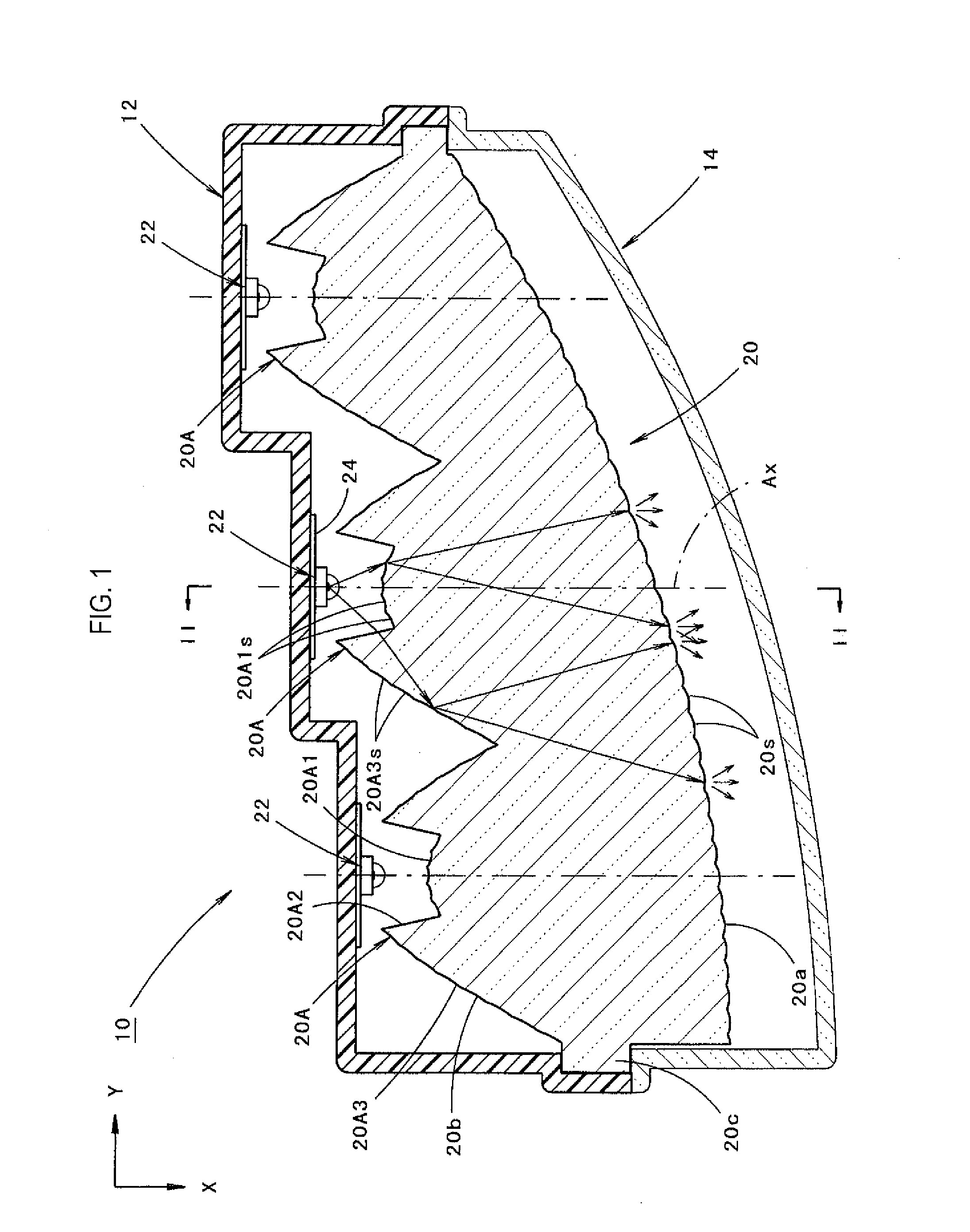
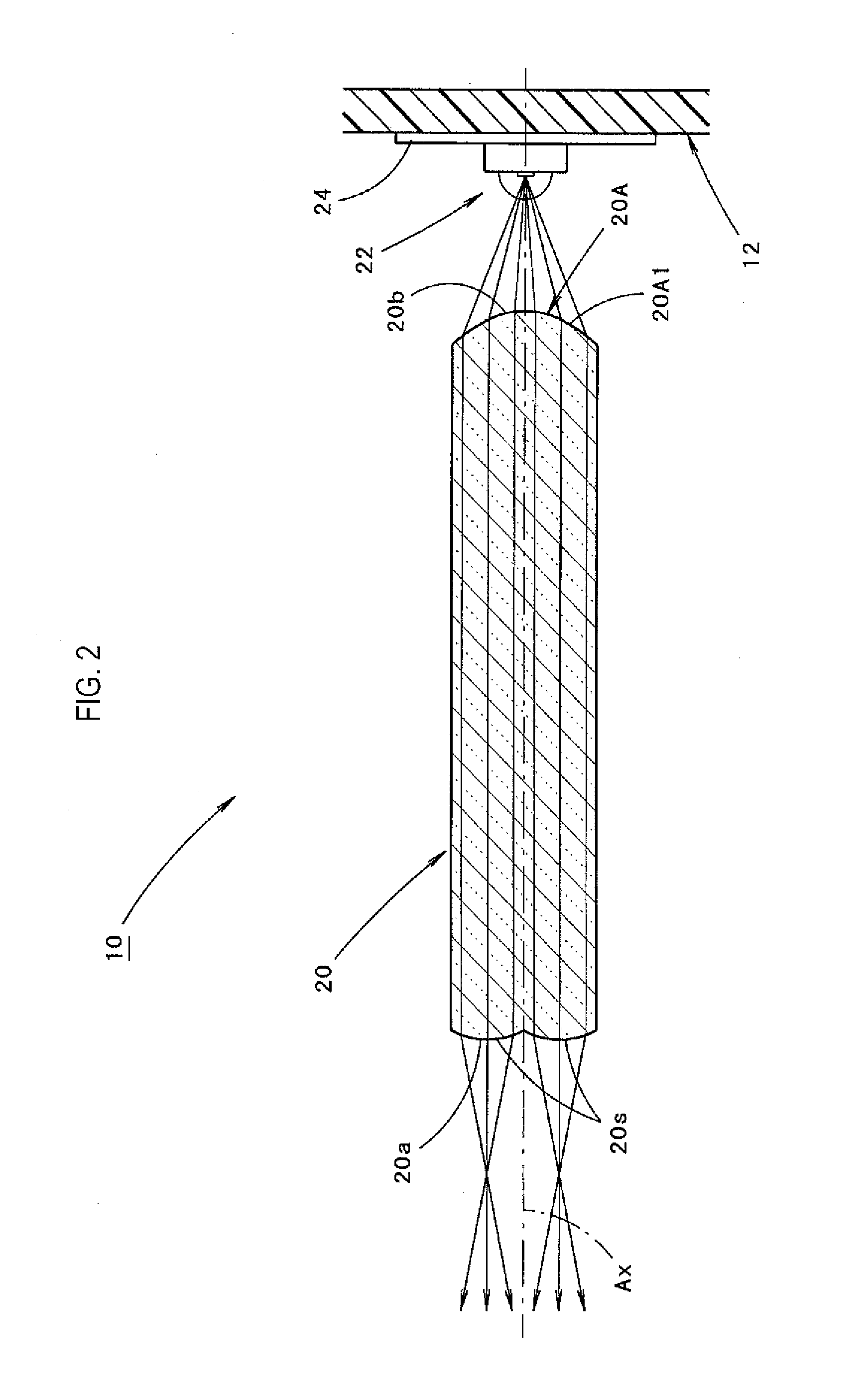
[0047]FIG. 1 is a sectional plan view showing a vehicular lamp 10 according to an embodiment of the invention. In addition, FIG. 2 is a sectional view taken along the line in FIG. 1.

[0048]As shown in these figures, the vehicular lamp 10 according to the embodiment is a tail lamp which is provided at a right rear end portion of a vehicle and has a configuration in which three light sources 22 and a light guide body 20 are incorporated in a lamp chamber which is defined by a lamp body 12 and a transparent light transmitting cover 14 which is attached to a front end opening portion of the lamp body 12.

[0049]It is noted that in the vehicular lamp 10 shown in FIG. 1, a direction denoted by an arrow X denotes a “front” (a “rear” of the vehicle), and a direction denoted by an arrow Y is a “rightward direction” which intersects the “front” at right angles.

[0050]The light transmitting cover 14 is f...


PUM


Abstract

A vehicular lamp includes a light source, and a light guide body having a front surface and a rear surface, configured to allow light emitted from the light source to enter from the rear surface and to exit through the front surface. The rear surface of the light guide body comprises, in a first plane extending in a front-to-rear direction, a first entrance portion configured to allow light emitted from the light source to enter in such a way as to be refracted to the front, second entrance portions situated at both sides of the first entrance portion and configured to allow light emitted from the light source to enter in such a way as to be refracted sideways, and reflecting portions configured to internally reflect light from the light source which enters from the second entrance portions to the front.

Description

CROSS-REFERENCE TO RELATED APPLICATION(S)[0001]The present application claims the benefit of priorities of Japanese Patent Application No. 2012-201926 filed on Sep. 13, 2012 and Japanese Patent Application No. 2013-083556 filed on Apr. 12, 2013. The disclosures of the applications are incorporated herein by reference.BACKGROUND[0002]1. Technical Field[0003]The present disclosure relates to a vehicular lamp which includes a light guide body.[0004]2. Related Art[0005]As a vehicular lamp including a light guide body, JP-A-2007-250401 describes a vehicular lamp in which light emitted from a light source is designed so as to enter a rear surface and exit through a front surface of a light guide body.[0006]JP-A-2006-48165 describes a vehicular lamp which is a signal lamp having a similar configuration to the aforesaid configuration. In this configuration, a rear surface of a light guide body includes a first entrance portion where light from a light source is allowed to enter so as to be ...

Claims


Application Information

Patent Timeline
Patent Type & Authority Applications(United States)
IPC IPC(8): F21S8/10F21V8/00F21W107/10
CPCG02B6/0033F21S48/00F21S43/14F21S43/20F21S43/26F21S43/239F21S43/243G02B19/0028F21S43/249F21S43/315F21S43/33F21S43/40G02B5/021G02B19/0014G02B19/0061F21S43/00
Inventor MOTOMURA, KENICHI
Owner KOITO MFG CO LTD
Why Eureka
Try Eureka