
Dynamic disinfection method for a vehicle drinking water tank

a technology for drinking water tanks and vehicles, applied in the direction of deodorants, cleaning using liquids, transportation and packaging, etc., can solve the problems of long maintenance intervals of drinking water tanks in vehicles, high economic costs for vehicle operators, and complicated fleet scheduling within the scope of fleet management. achieve uniform wetting of the inner surfa

Inactive Publication Date: 2014-03-13
AIRBUS OPERATIONS GMBH
View PDF8 Cites 1 Cited by
  • Summary
  • Abstract
  • Description
  • Claims
  • Application Information

AI Technical Summary

Benefits of technology

The patent describes a way to disinfect a vehicle's drinking water tank using a spray diffuser to create a continuous wetting film on the inner surface of the tank. This eliminates the need to fully fill the tank with disinfecting liquid and allows for quicker and more cost-effective disinfection. The method can also be used on areas within the drinking water system that are not connected to the main tank. Overall, the invention facilitates dynamic disinfection of contaminated surfaces and provides a more efficient and environmentally friendly solution for ensuring safe drinking water.

Problems solved by technology

Due to different standards, demands are placed on the reaction time, which leads to long maintenance intervals of the vehicles which contain the drinking water tank.
These known disinfection methods can only be carried out if the vehicle is stopped for a sufficiently long period, which complicates fleet scheduling within the scope of fleet management.
Furthermore, long periods of downtime mean that high economical costs are incurred for the vehicle operator.
Since the disinfection methods already known require the drinking water system to be filled completely, these methods also have a considerable effect on the environment in addition to high costs for the disinfecting active ingredient.

Method used


Image

  • Dynamic disinfection method for a vehicle drinking water tank
  • Dynamic disinfection method for a vehicle drinking water tank
  • Dynamic disinfection method for a vehicle drinking water tank

Examples


Embodiment Construction

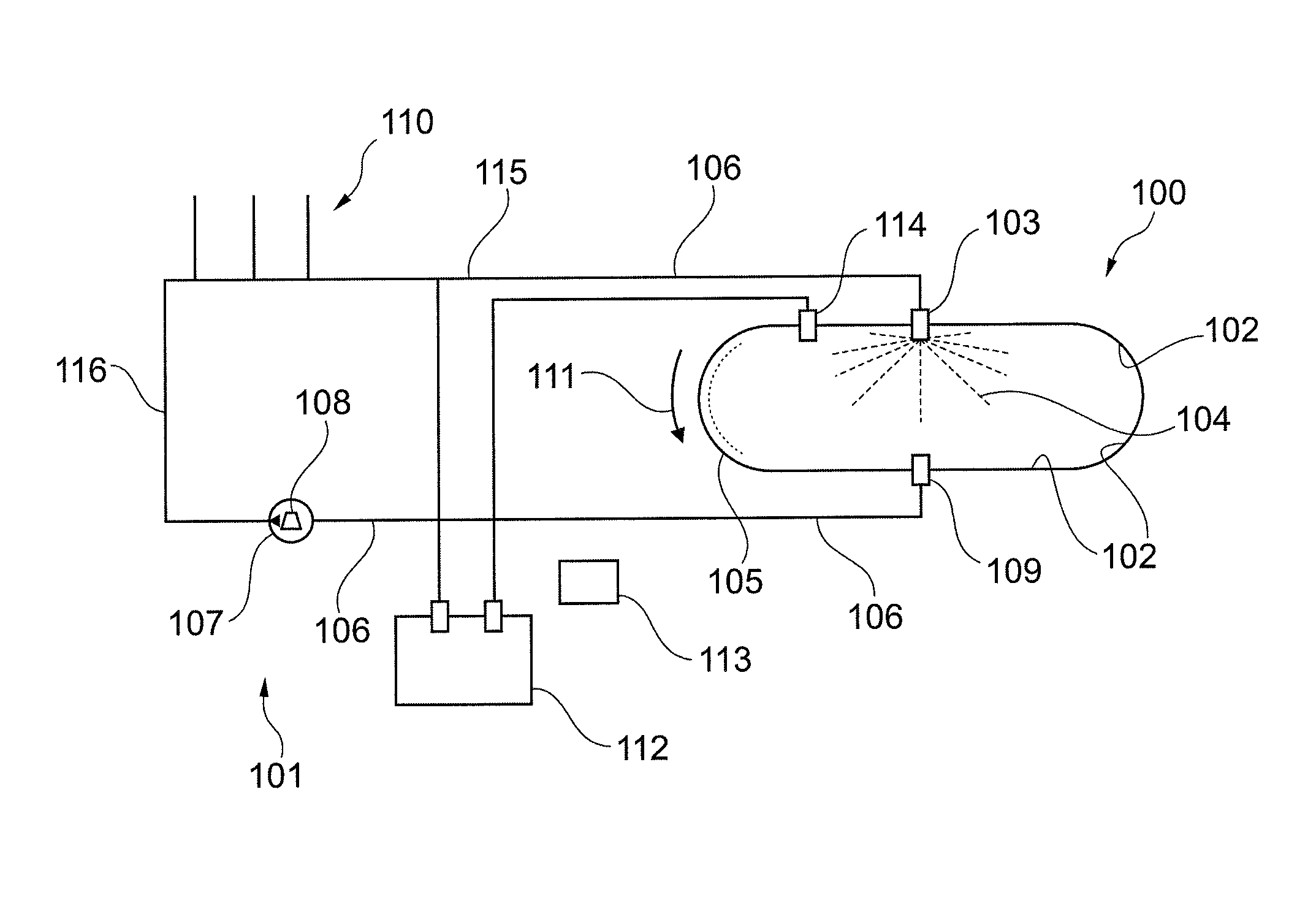
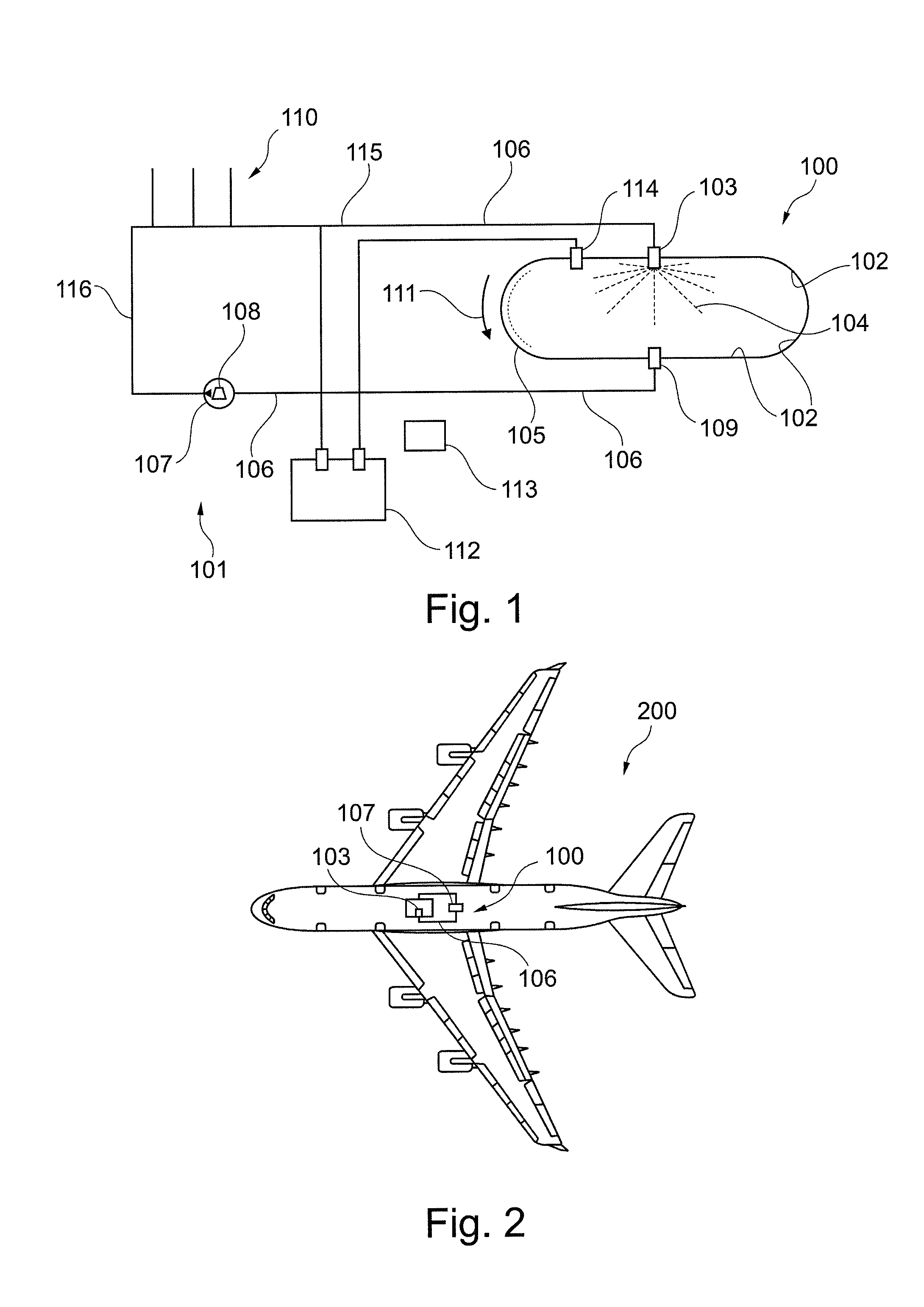
[0045]FIG. 1 shows a vehicle drinking water tank 100 to be filled with drinking water. The vehicle drinking water tank comprises, internally, a surface 102 and further comprises, internally, a spray diffuser 103 for wetting the surface inside the vehicle drinking water tank with a disinfecting liquid 104. As can be seen in FIG. 1, the spray diffuser 103 is arranged centrally in the ceiling of the vehicle drinking water tank. The disinfecting liquid can thus be distributed homogeneously in all spatial directions within the tank, if desired, so that substantially the entire surface inside the vehicle drinking water tank is provided with a liquid film 105, without the vehicle drinking water tank having to be filled completely with disinfecting liquid. The spray diffuser 103 may possibly also be designed as a moved diffuser, for example as a rotary diffuser, so as to wet the surface inside the tank. The arrow 111 indicates that a falling film of disinfecting liquid is concerned, which f...


PUM

PropertyMeasurementUnit
wettingaaaaaaaaaa
temperatureaaaaaaaaaa
reaction timeaaaaaaaaaa

Abstract

A method for disinfecting a vehicle drinking water tank is disclosed, wherein the method is designed for dynamic disinfection. By providing a vehicle drinking water tank with a spray diffuser, which is arranged inside the vehicle drinking water tank, the disinfecting liquid can be sprayed over substantially the entire inner surface of the tank. Partial filling of the drinking water tank with a disinfecting liquid starts the disinfection method. The dynamics of the disinfection method are achieved by spraying the disinfecting liquid in such a way that a moved film of disinfecting liquid is formed and wets an inner surface of the drinking water tank. Material transport at the inner wall of the tank is improved and mechanical shear forces act on the biofilm, which is to be removed and / or disinfected, in combination with the biochemical disinfection forces.

Description

CROSS-REFERENCE TO RELATED APPLICATIONS[0001]The present application is a continuation of International Application No. PCT / EP2012 / 058791, filed May 11, 2012, which claims priority from German Patent Application No. 10 2011 101 471.7 filed May 13, 2011 and claims the benefit of the filing date of United States Provisional Patent Application No. 61 / 485,776 filed May 13, 2011, the disclosures of which are hereby incorporated herein by reference.FIELD OF THE INVENTION[0002]The invention relates to the disinfection of a drinking water tank. In particular, the invention relates to a vehicle drinking water tank, an aircraft comprising a drinking water tank, and a dynamic disinfection method for a vehicle drinking water tank.TECHNICAL BACKGROUND[0003]In known methods, a static disinfection process is used for mobile water tanks. A disinfecting liquid is fed into the containers and lines to be disinfected so that the entire water system is filled completely with disinfecting liquid. The dis...

Claims


Application Information

Patent Timeline
Patent Type & Authority Applications(United States)
IPC IPC(8): B60R15/00A61L2/18B60N3/18
CPCB60R15/00A61L2/18B60N3/18B64D11/04C02F1/50C02F2201/008C02F2209/02C02F2303/04B64D11/02C02F1/68
Inventor SCHREINER, AXELCAVARERO, PAOLO
Owner AIRBUS OPERATIONS GMBH
Learn More