

Small diameter laparoscopic tool having releasable tip
a laparoscopic tool and small diameter technology, applied in the field of surgical tools, can solve the problems of limited utility, unreliable, and difficult unplanned procedures, and achieve the effects of reducing the risk of complications, limiting the utility of the surgical tool, and not being robus
Active Publication Date: 2014-03-13
UNIV OF SOUTH FLORIDA +1
View PDF4 Cites 9 Cited by
- Summary
- Abstract
- Description
- Claims
- Application Information
AI Technical Summary
Benefits of technology
The patent describes a device that allows for the controlled deployment of a tool through the umbilicus and into the abdomen. The device has a tip with jaws that can be opened and closed using a control wire, which is placed through the abdominal incision. The device also includes a small diameter sheath that can be connected to the tip using a docking mechanism. The device can be introduced through a large diameter sheath and has a bias that can be unloaded to deploy the tool. An alternative embodiment includes a second sheath with an opening that can be aligned with a tip dispenser to unload the bias and deploy the tool.
Problems solved by technology
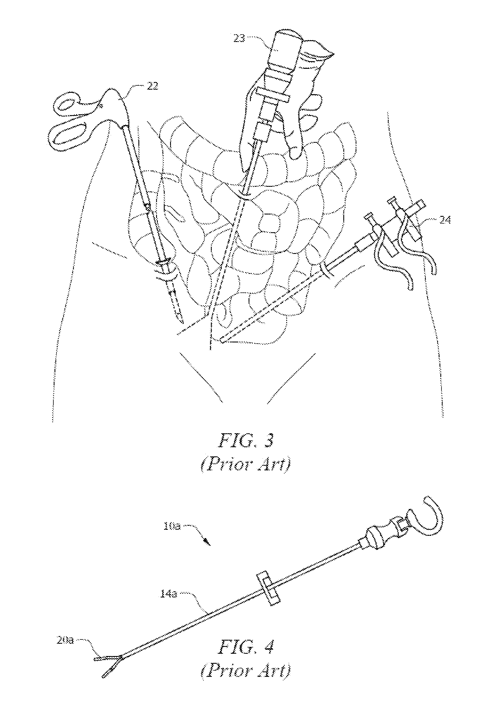
Such undepicted procedures are difficult because the tools must be used in close proximity to one another.
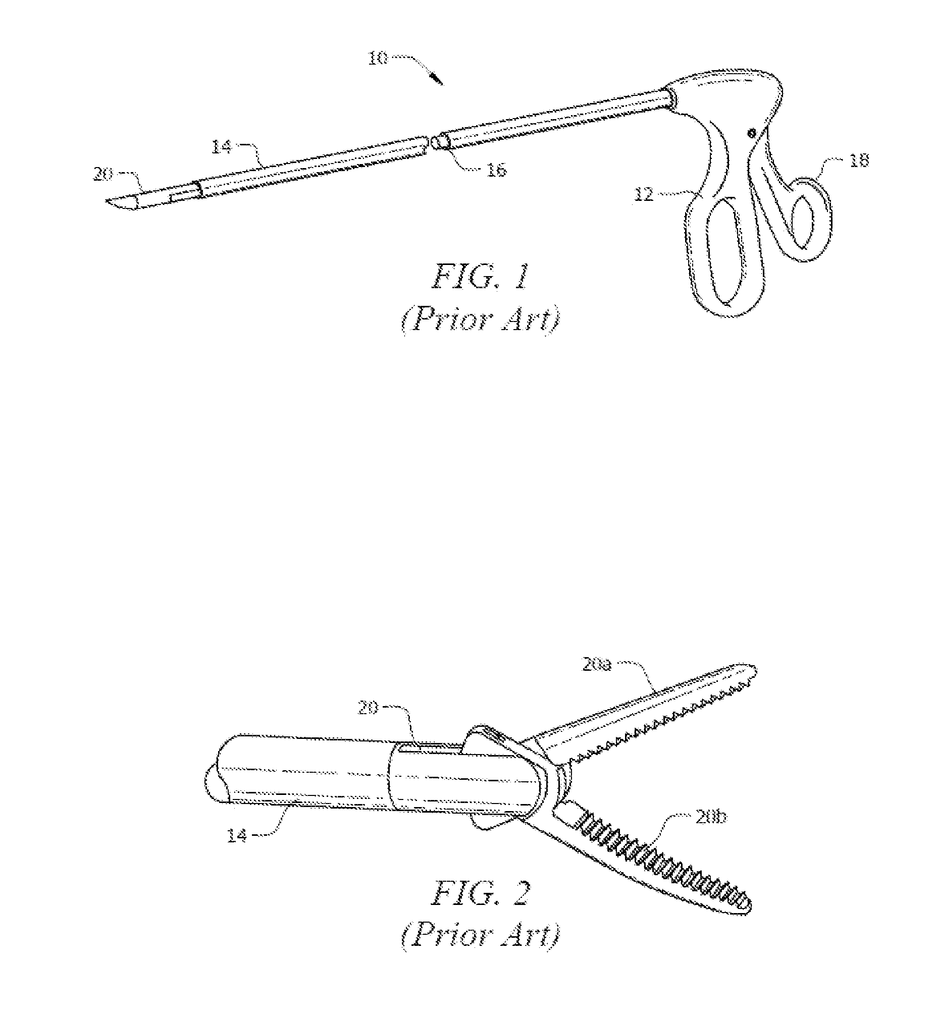
However, the small size of tip 20a limits its utility, i.e., it is not robust because it has limited surface area or limited force capability for many common surgical procedures.
Moreover, the smallest diameter tool, having a sheath diameter of 2.5 mm, is still too large to reduce the likelihood of scarring.
Method used
View moreImage
Smart ImageViewing Examples

Examples
first embodiment
[0084]FIGS. 10-12 also indicate that tip dispensers 50 need not be in axial alignment with one another as in the first embodiment Handle 12a in FIG. 12 may be supplanted by handle 12 of a prior art handle.
second embodiment
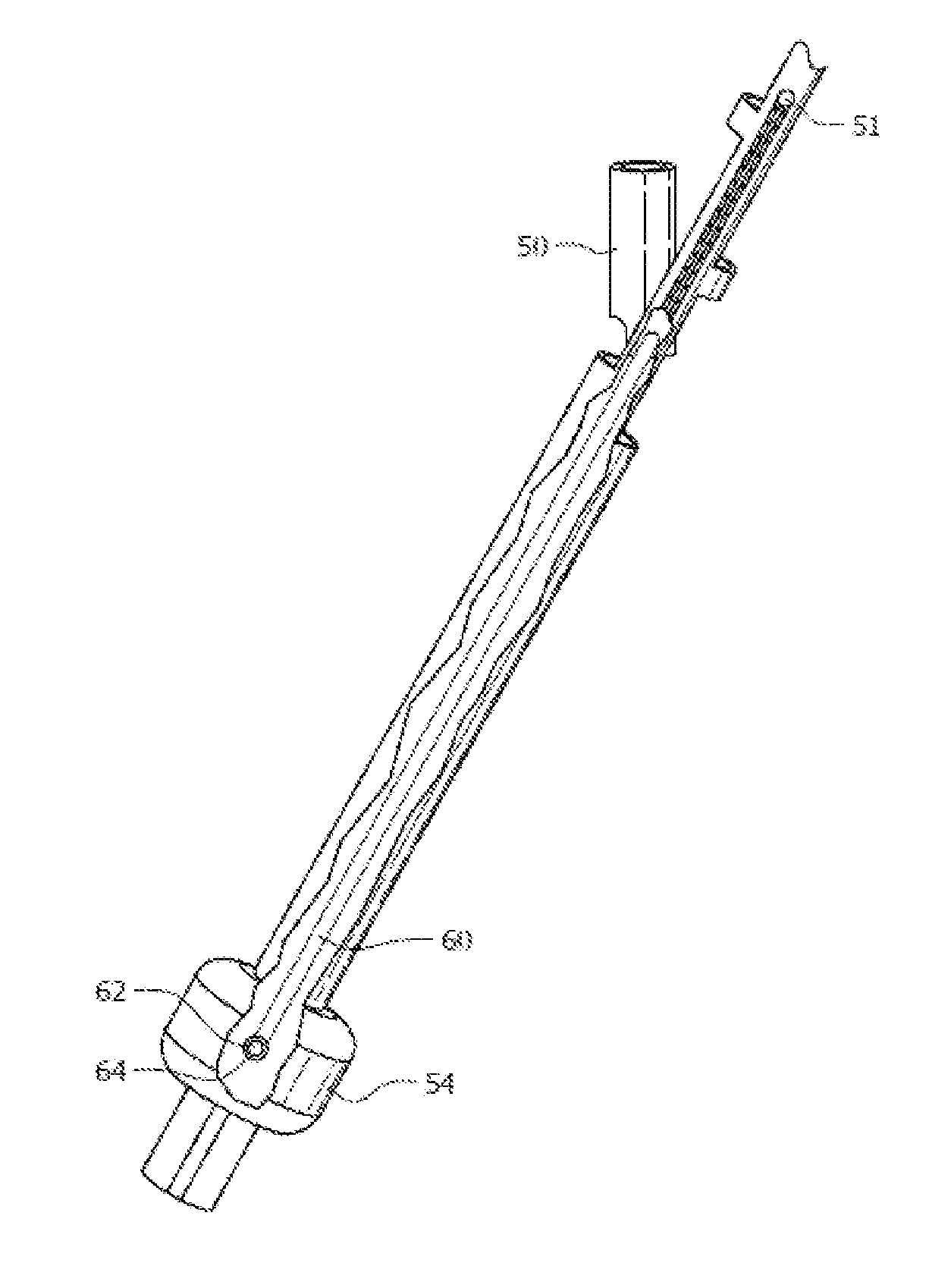
[0085]FIG. 13 is a side elevational view depicting the parts of the second embodiment and a laparoscope in their assembled configuration.
[0086]FIG. 14 is an exploded perspective view of the parts depicted in FIG. 13.
Login to View More PUM
 Abstract
A laparoscopy tool includes a sheath and a control wire slideably disposed within a lumen of the sheath. The sheath has a diameter of less than 1.6 mm and is introduced through an abdominal incision. A handle axially displaces the control wire within the lumen and operates a conventional tip with wire-controlled opposing jaws that is introduced through the umbilicus and has a bore formed in its trailing end. A first set of blades in the bore engage grooves formed in the leading end of the control wire and a second set of blades engages the sheath to prevent sheath retraction. A cam displaces the second set of blades away from the sheath for sheath introduction and removal, and toward the sheath to prevent sheath retraction. The tip is removed through the umbilicus and the tool is removed through the abdominal incision when the surgery is completed.
Description
CROSS-REFERENCE TO RELATED APPLICATIONS[0001]This nonprovisional application is a continuation of prior filed International Application PCT / US2012 / 033566 filed Apr. 13, 2012, which claims priority to U.S. provisional application No. 61 / 474,859 entitled “Small Diameter Laparoscopic Tool Having Releasable Tip,” filed on Apr. 13, 2011 by the same inventor.BACKGROUND OF THE INVENTION[0002]1. Field of the Invention[0003]This invention relates, generally, to surgical tools. More particularly, it relates to small diameter laparoscopic surgical tools.[0004]2. Description of the Prior Art[0005]FIG. 1 depicts conventional laparoscopic surgery tool 10 having stationary handle 12 connected to sheath 14. Control rod or wire 16 is slideably disposed within a lumen of sheath 14 and its proximal end is connected to actuating handle 18 that is pivotally connected to stationary handle 12. Control rod or wire 16 is pushed or pulled within the lumen so that it extends or retracts relative to a distal f...
Claims
Login to View More Application Information
Patent Timeline
 Patent Type & AuthorityApplications(United States)
IPC IPC(8): A61B17/3205
CPCA61B17/3205A61B1/00087A61B1/00101A61B1/3132A61B17/3421A61B2017/00362A61B2017/2931A61B17/320016A61B17/3423A61B2017/2946
InventorHART, STUART RICHARDSIMOES, MARIO A.HIPOL, PHILIP JAMESHUFFORD, KEVIN
OwnerUNIV OF SOUTH FLORIDA