Themal dispalcement compensating device of machine tool

Active Publication Date: 2014-03-13
FANUC CORP
View PDF3 Cites 71 Cited by
  • Summary
  • Abstract
  • Description
  • Claims
  • Application Information

AI Technical Summary

Benefits of technology

[0022]The present invention can provide a thermal displacement compensation device of a machine tool which enables a function of predicting a thermal displacement amount from, for example, an operation of the machine tool and a temperature of each part and compensating the thermal compensation amount to reduce an error of a setting of adjustment of the thermal displacement compensati

Problems solved by technology

In some cases, a function of calculating and compensating a thermal displacement amount from, for example, an operation of a machine tool or a temperature of each part cannot more accurately calculate the thermal displacement amount due to surrounding environment such as a coolant or an outside air temperature, and therefore an error (compensation error) between the thermal displacement compensation amount and an actual thermal displacement amount becomes significant, and the thermal displacement amount cannot be accurately compensated.
Hence, a thermal displacement compensation amount is compensated by adding a position command value to the thermal displacement compensation amount in some cases and a thermal displacement compensation amount is compensated by subtracting a position

Method used


Image

  • Themal dispalcement compensating device of machine tool
  • Themal dispalcement compensating device of machine tool
  • Themal dispalcement compensating device of machine tool

Examples


Embodiment Construction

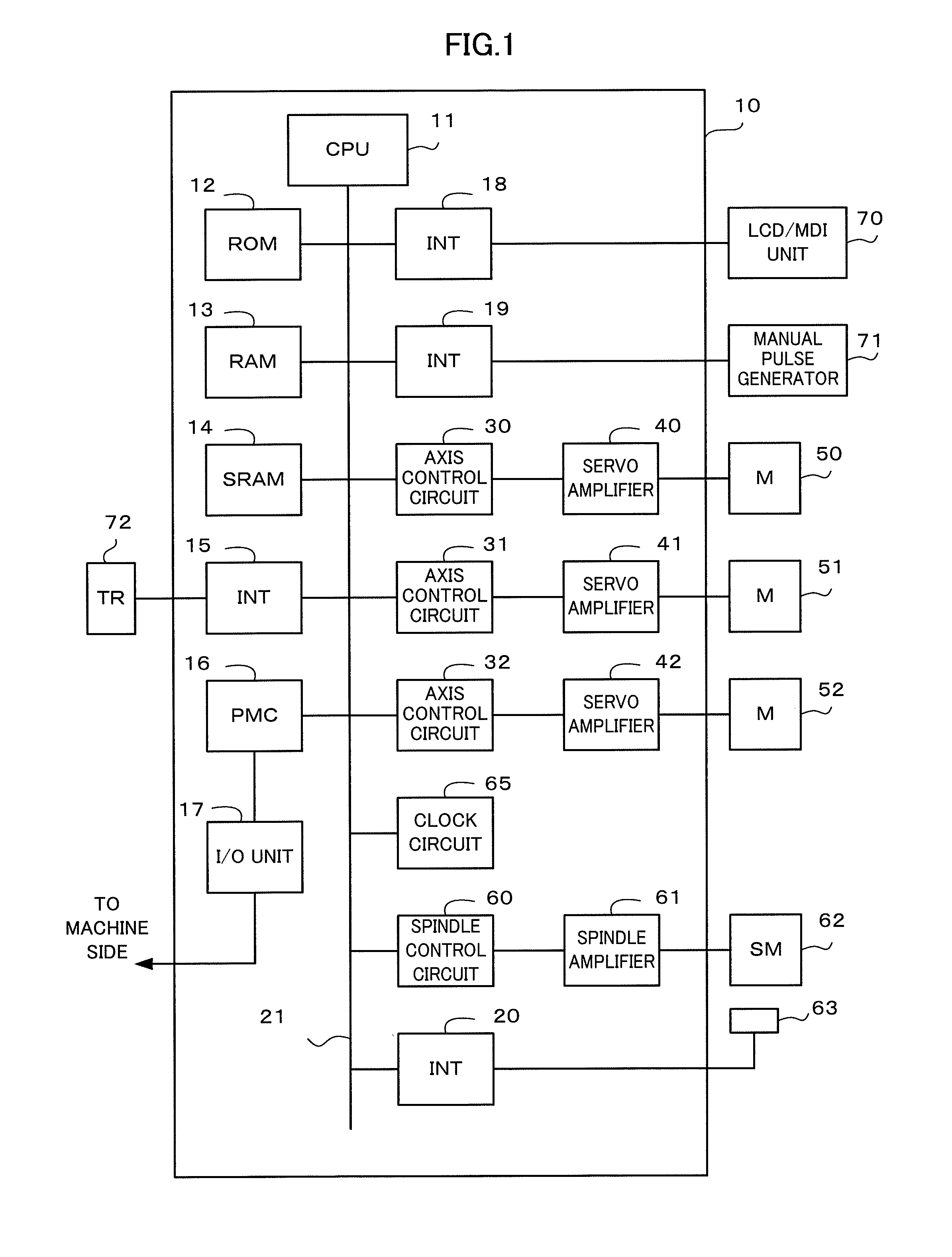
[0031]A thermal displacement compensation device of a machine tool according to the present invention is formed by a numerical controller which controls the machine tool. An outline of this numerical controller will be described using a block diagram of FIG. 1.

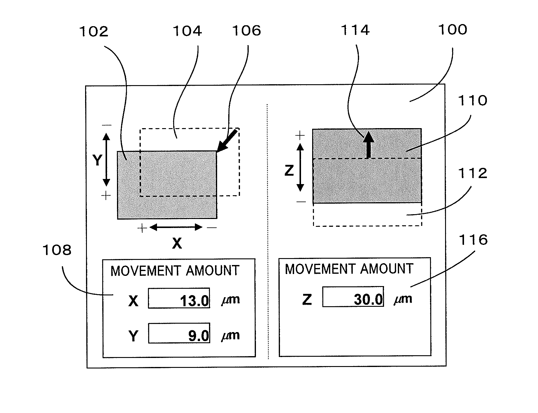
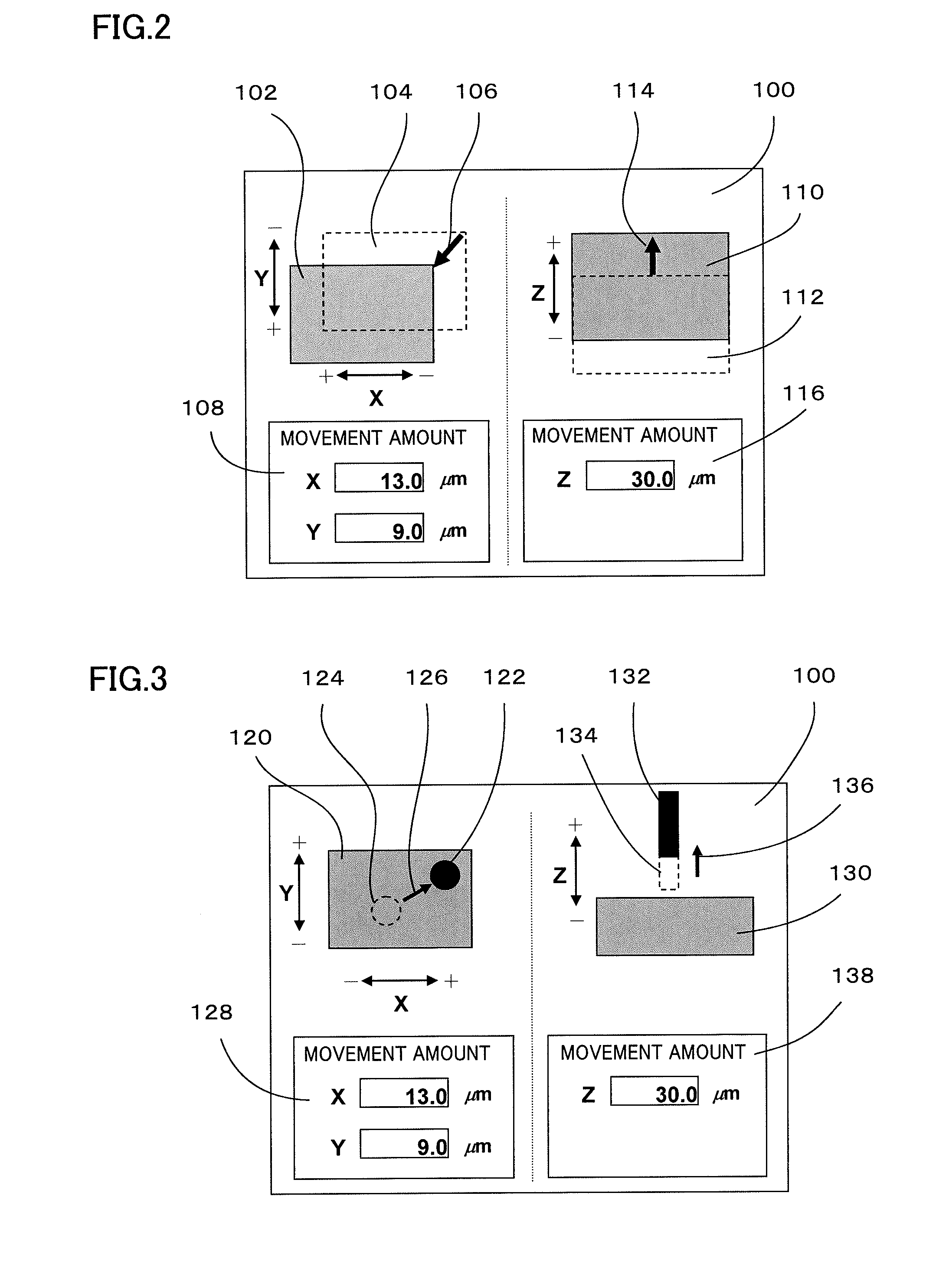
[0032]A processor (CPU) 11 of a numerical controller 10 reads a system program stored in a ROM 12 through a bus 21, and entirely controls the numerical controller 10 according to this system program. An LCD / MDI unit 70 is a manual input device with a display device, and displays on this display device (a liquid crystal display device LCD) a display example illustrated in FIG. 2 or 3. This LCD / MDI unit 70 has a function of moving a display position of a display image illustrated in FIG. 2 or 3 according to an operator's specific operation (such as a cursor key input, a software key input or a dragging operation) or a function of inputting a numerical value of a movement amount. A RAM 13 stores temporary calculation data, displa...


PUM


Abstract

A position command value is compensated by predicting a thermal displacement amount of each part of a machine tool and adding a thermal displacement compensation amount which cancels the predicted thermal displacement amount to the position command value of a feed axis. This thermal displacement compensation amount is adjusted from the error amount between this compensated position command value and an actual machining point. Upon adjustment of this thermal displacement compensation amount, it is possible to determine whether to increase or decrease the thermal displacement amount based on a direction in which an operator moves a tool image or a workpiece image on a screen.

Description

BACKGROUND OF THE INVENTION[0001]1. Field of the Invention[0002]The present invention relates to a thermal displacement compensation device of a machine tool which improves working efficiency upon adjustment of the amount of thermal displacement compensation amount.[0003]2. Description of the Related Art[0004]In some cases, a function of calculating and compensating a thermal displacement amount from, for example, an operation of a machine tool or a temperature of each part cannot more accurately calculate the thermal displacement amount due to surrounding environment such as a coolant or an outside air temperature, and therefore an error (compensation error) between the thermal displacement compensation amount and an actual thermal displacement amount becomes significant, and the thermal displacement amount cannot be accurately compensated. In general, when the compensation error becomes significant due to an external factor, compensation precision is improved by adjusting the ther...

Claims


Application Information

Patent Timeline
IPC IPC(8): G05B13/02
CPCG05B13/02B23Q11/0007B23Q15/013G05B19/404G05B2219/37555G05B2219/49207
Inventor ENDOU, TAKAHIROMAEKAWA, SUSUMU
Owner FANUC CORP
Why Eureka
Try Eureka