
Capacitance probe

a technology of capacitance probes and probes, which is applied in the direction of instruments, gas-turbine engine testing, structural/machine measurement, etc., can solve the problems of limiting the locations requiring significant additional re-operation of the outer air seal

Active Publication Date: 2014-03-20
RAYTHEON TECH CORP
View PDF23 Cites 13 Cited by
  • Summary
  • Abstract
  • Description
  • Claims
  • Application Information

AI Technical Summary

Benefits of technology

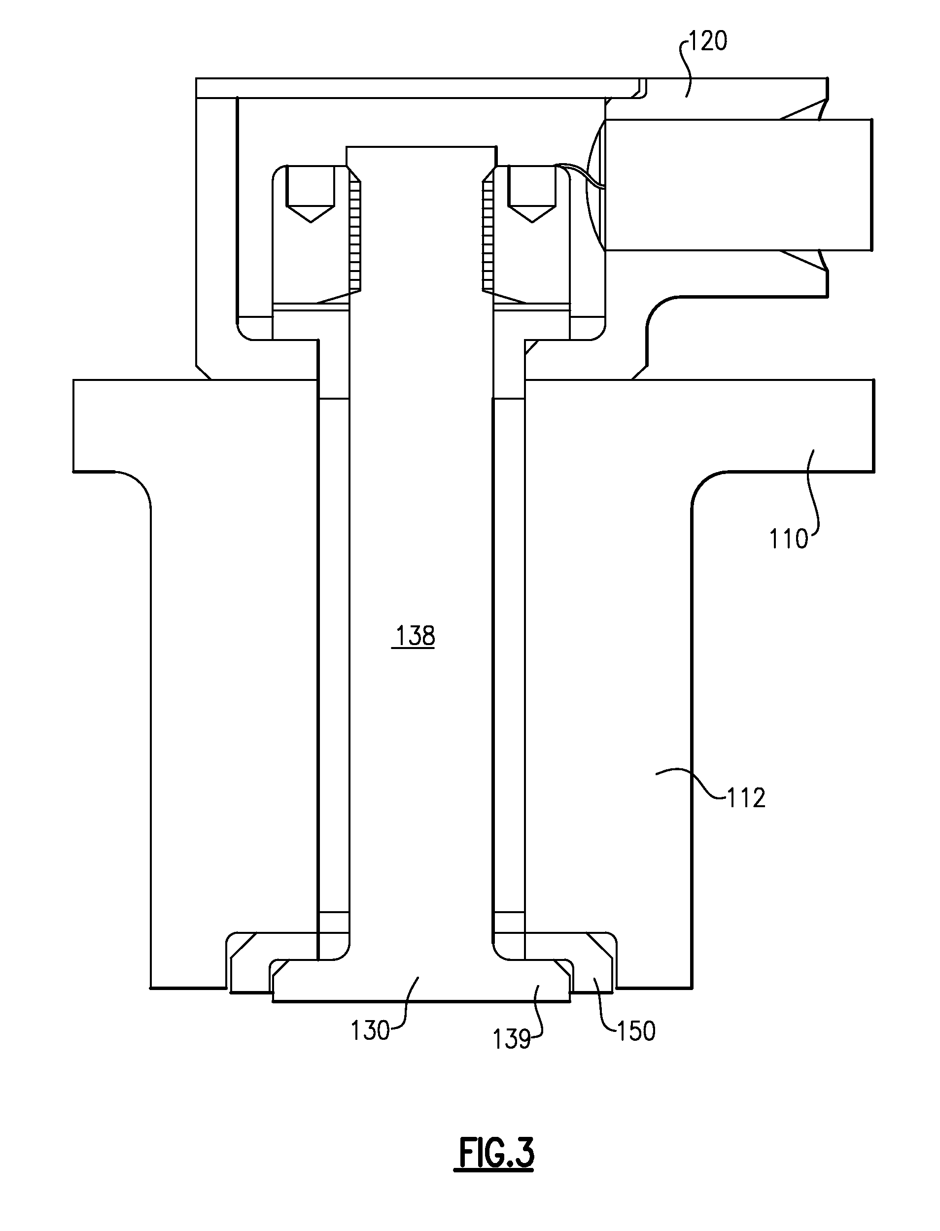
The patent describes an outer air seal case for a turbine engine that includes a sensor rod for measuring clearance between parts. The case includes a sensor rod that is anchored in position within the case using a nut and a lead egress. The case also includes a sensor rod support pad that maintains the sensor rod in position within the case. The sensor rod is fixed to the nut using a weld, which ensures tension on the sensor rod. The case also includes a lead egress and a cap. The technical effect of this invention is to provide a reliable and accurate means for measuring clearance between parts in a turbine engine.

Problems solved by technology

Existing tip clearance probe arrangements require the outer air seal casing to further accommodate the housing of the tip clearance probe, thereby limiting the locations on the outer air seal that can accept the tip clearance probe and requiring significant additional re-operation of the outer air seal.

Method used


Image

  • Capacitance probe
  • Capacitance probe
  • Capacitance probe

Examples


Embodiment Construction

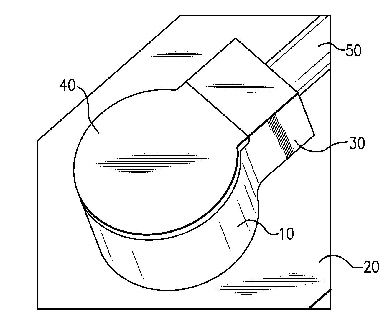
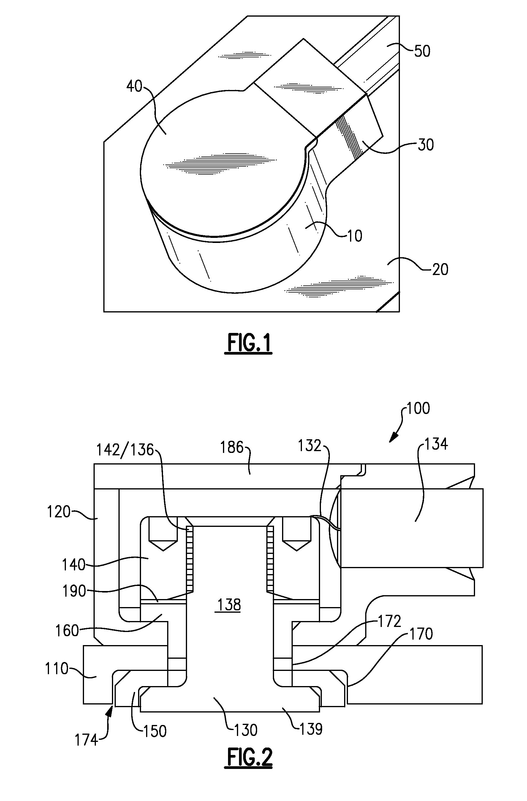
[0030]FIG. 1 illustrates a capacitance probe 10 that is built into a metal housing 20 such as the housing of an outer air seal (OAS) for a turbine engine. The illustrated capacitance probe 10 is a tip clearance probe, however it is understood that similar capacitance probes 10 could be used for alternative clearance measurements. A sensor portion of the capacitance probe 10 is partially enclosed within a partial sensor housing 30. A sensor cap 40 is affixed to the top of the partial sensor housing 30, and encloses the sensor portion within the partial sensor housing 30. The sensor portion detects the clearance within the metal housing 20 by determining the capacitance between the sensor face and the target, which in the illustrated example is a blade tip. An electric lead 50 exits the housing 30 via a lead egress and connects the sensor portion within the partial sensor housing 30 to a controller (not pictured), or to any other system that is operable to receive and act upon sensor ...


PUM


Abstract

A capacitance based clearance probe has a partial sensor housing mounted on a surface and a sensor rod anchored in the partial sensor housing. The sensor rod extends into a sensor opening in the surface such that the partial sensor housing and the surface combine to operate as a complete sensor housing.

Description

BACKGROUND OF THE INVENTION[0001]The present disclosure is directed generally toward capacitance based clearance probes, and more specifically toward a capacitance based clearance probe built into a metal surface.[0002]Gas turbine engines, such as those utilized in commercial aircraft, include multiple rotors and stators configured to enable optimal operation. Turbine engines maintain an optimal clearance (distance) between the tips of the rotors and an outside diameter of a gas path within the turbine engine, and thereby provide the conditions necessary to achieve a desired performance.[0003]The gas turbine engine performance is validated, in part, by measuring the blade tip clearance. In order to measure the tip clearance, one or more tip clearance probes are installed in the outer air seal wall of the turbine engine. As the tip clearance probes are incorporated onto the outer air seal of the gas turbine after the outer air seal has been manufactured, it is necessary to re-operate...

Claims


Application Information

Patent Timeline
IPC IPC(8): G01M15/14G01B7/14
CPCG01B7/22
Inventor WARREN, ELI COLEBENOIT, COREY
Owner RAYTHEON TECH CORP
Learn More