Article with a dynamic frame formed with aligned pigment flakes

a dynamic frame and pigment flakes technology, applied in the direction of coatings, printing, inks, etc., can solve the problems of optical devices that do not transmit light, optical devices that are intended to be noticed are not widely known, and the security risk of possible transfer of patches to forged documents is not known

Active Publication Date: 2014-03-20
VIAVI SOLUTIONS INC
View PDF2 Cites 52 Cited by
  • Summary
  • Abstract
  • Description
  • Claims
  • Application Information

AI Technical Summary

Benefits of technology

[0201]Advantageously, in a printed article with a dynamic stereoscopic effect related to an optical parallax of the bright frame, an observer may see the bright frame as floating in a distance of 3-8 mm from the substrate. Optical devices disclosed in this application may cause illusory flotation of graphical elements of the device, as well as motion and morphing of optical elements. The graphics printed on a banknote plays an important role in the note's appearance and its acceptance by the public. The dynamic optical component enhances the appearance of the graphical component by managing the visual perception: stereopsis, reference frames and occlusion. It is desirable to avoid interruption of the graphical image on the surface of the note with magnetic ink, but to use the magnetic ink to enhance the image with depth, motion and flotation so that the optical effect produced by the flakes serves as a reference frame for the graphics, which problem is solved by using the low concentrations of the magnetic ink, the frame pattern which concentrates attention of an observer in the center of the frame, and an arching alignment of the pigment flakes in the cross sections of the frame pattern which concentrate reflected light into a bright dynamic frame, whereas the dynamic quality of the frame increases the attention of the observer.

Problems solved by technology

Unfortunately, some optically variable devices that are intended to be noticed are not widely known because the optically variable aspect of the device is not sufficiently dramatic.
The resulting optical devices do not transmit light.
Sometimes they are referred to as security patches, and there is a security risk associated with possible transfer of a patch to a forged document.
Additionally, the opaque security devices formed of magnetic pigments may be undesirable because they essentially hide the background pattern whereas intrinsic Guilloché patterns are widely relied upon in banknote printing.

Method used


Image

  • Article with a dynamic frame formed with aligned pigment flakes
  • Article with a dynamic frame formed with aligned pigment flakes
  • Article with a dynamic frame formed with aligned pigment flakes

Examples


Embodiment Construction

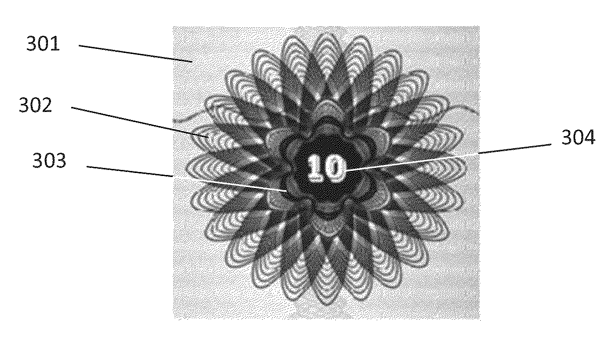
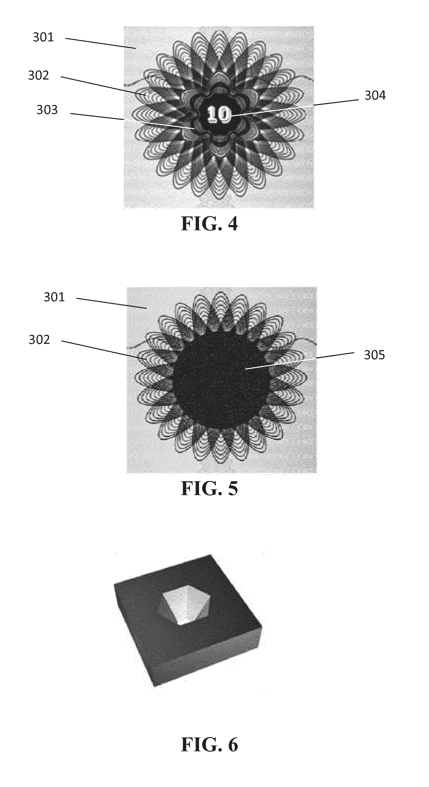
[0077]A previously unknown effect has been discovered by the inventors in their experiments with optically variable frames surrounding symbols printed in regular ink: a bright frame formed by light reflected from magnetically aligned pigment flakes appears to float parallel to the substrate whereon the magnetic ink is printed. Unexpectedly, the bright frame appears to move above or below the surface of the substrate.

[0078]The purpose of the experiments was to combine optical effects generated by magnetically aligned flakes with conventional printed graphical images; the inventors were using optically variable images as frames surrounding printed images. The optically variable frames simultaneously serve as security features per se, because they are difficult to reproduce, as decorative elements for their spectacular optical effects, as well as for attracting a human eye to the image surrounded by the frame, the way guilloche patterns highlight denomination numerals on banknotes.

[007...


PUM

PropertyMeasurementUnit
anglesaaaaaaaaaa
anglesaaaaaaaaaa
angleaaaaaaaaaa

Abstract

An article includes a substrate and a graphical component forming an image and an optical component which includes magnetic pigment flakes aligned so as to form a frame pattern which surrounds the image. When light is incident upon the pigment flakes from a light source, light reflected from the frame pattern forms a dynamic frame which surrounds the image and appears to move as the substrate is tilted with respect to the light source. The image appears to be stationary when the dynamic frame appears to move.

Description

CROSS-REFERENCE TO RELATED APPLICATIONS[0001]The present invention claims priority from U.S. Provisional Patent Application No. 61 / 585,954 filed Jan. 12, 2012, incorporated herein by reference.TECHNICAL FIELD[0002]The present invention relates generally to optically variable devices and, more particularly, to aligning or orienting magnetic flakes in a painting or printing process in order to obtain an illusive optical effect.BACKGROUND OF THE INVENTION[0003]Optically variable devices are used in a wide variety of applications, both decorative and utilitarian; for example, such devices are used as security devices on commercial products. Optically variable devices can be made in numerous ways to achieve a variety of effects. Examples of optically variable devices include the holograms imprinted on credit cards and authentic software documentation, color-shifting images printed on banknotes and enhancing the surface appearance of items such as motorcycle helmets and wheel covers.[0004...

Claims


Application Information

Patent Timeline
Patent Type & Authority Applications(United States)
IPC IPC(8): B44F1/02B42D15/00B44F1/10C09D7/61
CPCB44F1/02B42D15/0013B44F1/10B42D25/29B42D25/369B42D25/378B42D25/41C09D7/61B05D3/207B05D5/061B41M3/14B41M7/0072C09D5/29C09D5/36C09D11/00G02B5/08B41M1/00B42D25/342H01F41/0253B42D25/00
Inventor RAKSHA, VLADIMIR P.HYNES, JOHNHOLDEN, LAURENCECOOMS, PAUL G.
Owner VIAVI SOLUTIONS INC
Why Eureka
Try Eureka