Imaging device with a plurality of pixel arrays

a technology of image capture and pixel array, applied in the field of optics, can solve the problems of limited field of view and limited exposure time of conventional digital imaging devices

Active Publication Date: 2014-03-20
GOOGLE LLC
View PDF12 Cites 119 Cited by
  • Summary
  • Abstract
  • Description
  • Claims
  • Application Information

AI Technical Summary

Problems solved by technology

Conventional digital imaging devices may also have a limited field of view for a given image capture.
Conventional digital imaging devices may also be limited to a given number of image captures in a specific amount of time (e.g. 30 frames per second).
Some conventional digital imaging devices are also limited to a given exposure time in a given image capture.
This may limit the dynamic range of the image captured.

Method used


Image

  • Imaging device with a plurality of pixel arrays
  • Imaging device with a plurality of pixel arrays
  • Imaging device with a plurality of pixel arrays

Examples


Embodiment Construction

[0020]Embodiments of a system and method for capturing images are described herein. In the following description, numerous specific details are set forth to provide a thorough understanding of the embodiments. One skilled in the relevant art will recognize, however, that the techniques described herein can be practiced without one or more of the specific details, or with other methods, components, materials, etc. In other instances, well-known structures, materials, or operations are not shown or described in detail to avoid obscuring certain aspects.

[0021]Reference throughout this specification to “one embodiment” or “an embodiment” means that a particular feature, structure, or characteristic described in connection with the embodiment is included in at least one embodiment of the present invention. Thus, the appearances of the phrases “in one embodiment” or “in an embodiment” in various places throughout this specification are not necessarily all referring to the same embodiment....


PUM


Abstract

An imaging device includes a first pixel array arrange to capture a first image and a second pixel array arranged to capture a second image. The first pixel array and the second pixel array face substantially a same direction. The imaging device also includes shutter control circuitry which is coupled to the first pixel array to initiate a first exposure period of the first pixel array to capture the first image. The shutter control circuitry is also coupled to the second pixel array to initiate a second exposure period of the second pixel array to capture the second image. The imaging device also includes processing logic coupled to receive first pixel data of the first image and coupled to receive second pixel data of the second image. The processing logic is configured to generate at least one image using the first pixel data and the second pixel data.

Description

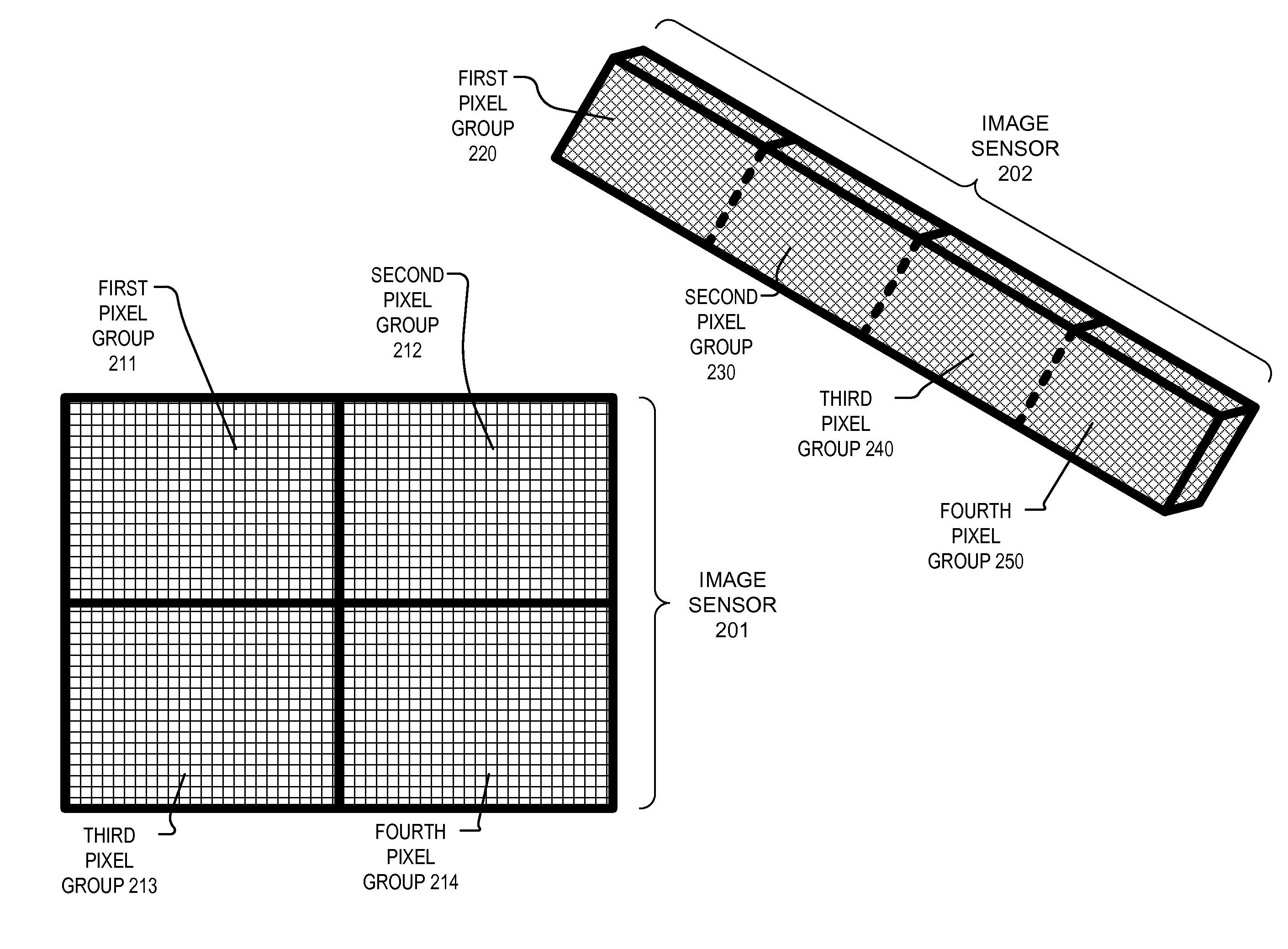
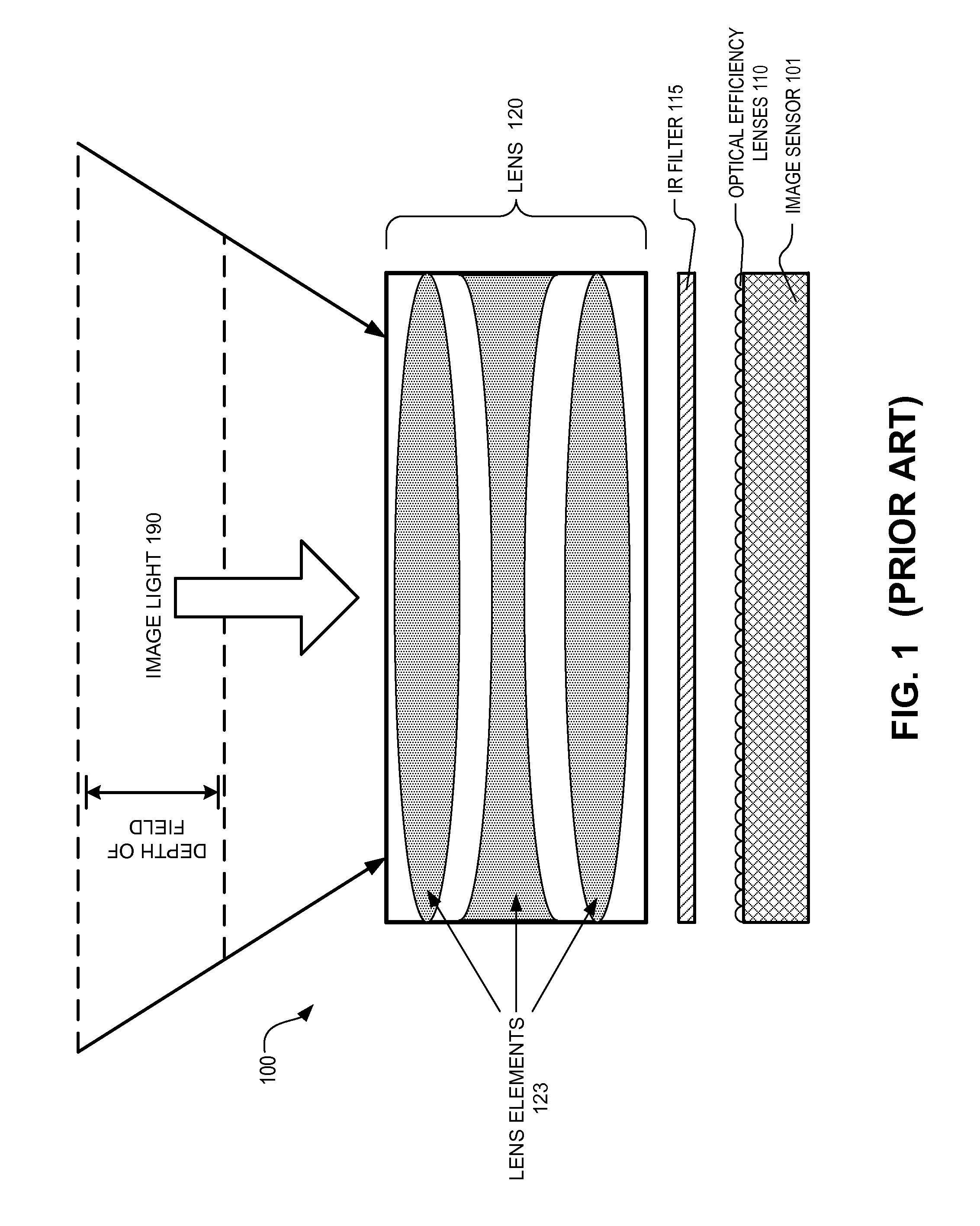
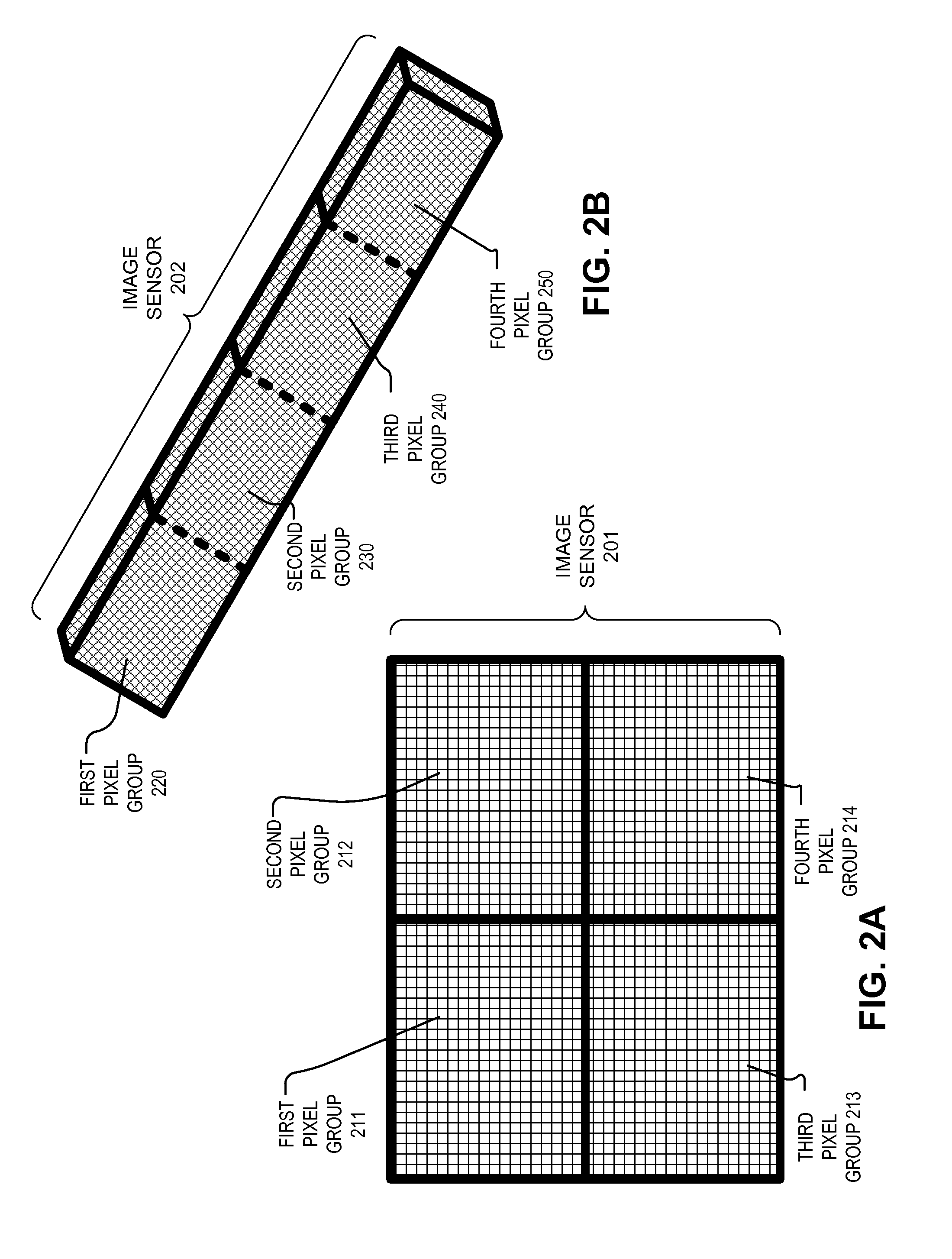
TECHNICAL FIELD[0001]This disclosure relates generally to optics, and in particular but not exclusively, relates to digital imaging devices.BACKGROUND INFORMATION[0002]Conventional digital imaging devices or cameras have a lens (which may include multiple lens elements) that focuses image light onto an image sensor that measures the image light and generates an image based on the measurements. FIG. 1 illustrates a common configuration for a digital imaging device 100. FIG. 1 includes an image sensor 101 and optical efficiency lenses 110 disposed over image sensor 101. Optical efficiency lenses 110 function to draw as much light as possible into the pixels for measurement. Optical efficiency lenses 110 may be microlenses disposed over each pixel of image sensor 101. An infrared (“IR”) filter 115 may be disposed over optical efficiency lenses 110 and image sensor 101 to filter out IR light from being measured by image sensor 101. Lens 120 is disposed over image sensor 101 to focus ima...

Claims


Application Information

Patent Timeline
Patent Type & Authority Applications(United States)
IPC IPC(8): H04N5/228
CPCH04N23/54H04N23/50H04N23/60H04N23/951H04N23/741H04N25/41H04N23/69H04N23/51H04N23/73G02B13/0015G02B27/0172G02B2027/0178H04N5/265
Inventor MIAO, XIAOYU
Owner GOOGLE LLC
Why Eureka
Try Eureka