
System and Method for Addressing a Pneumatic Emergency in a Helper Locomotive

a technology of helper locomotive and emergency response, which is applied in the direction of braking system, process and machine control, instruments, etc., can solve the problems exposing railroad personnel to the risk of serious injury, etc., and improving braking safety. , the effect of reducing the recovery time of the brake system

Active Publication Date: 2014-03-20
WABTEC HLDG CORP
View PDF64 Cites 8 Cited by
  • Summary
  • Abstract
  • Description
  • Claims
  • Application Information

AI Technical Summary

Benefits of technology

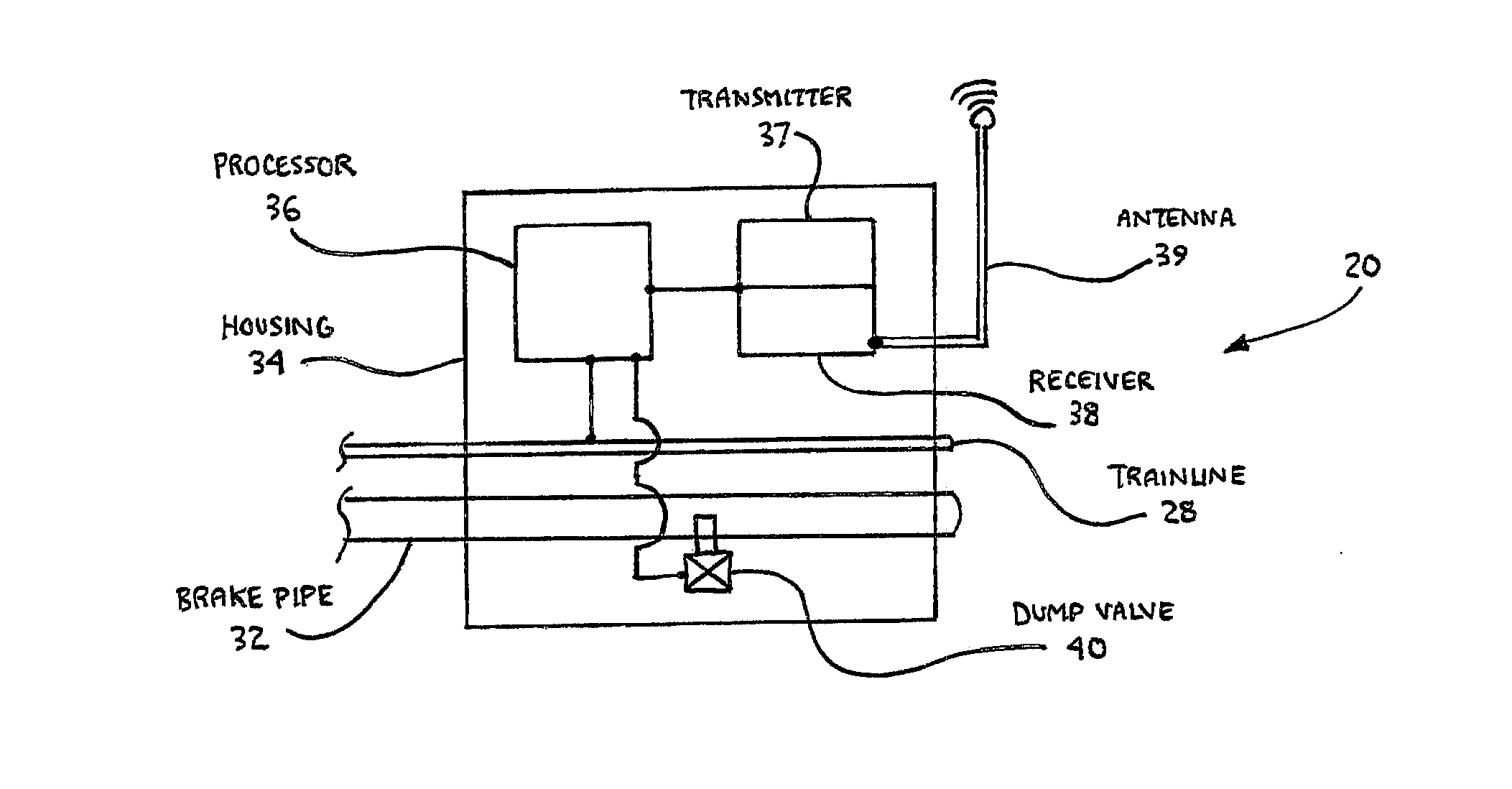
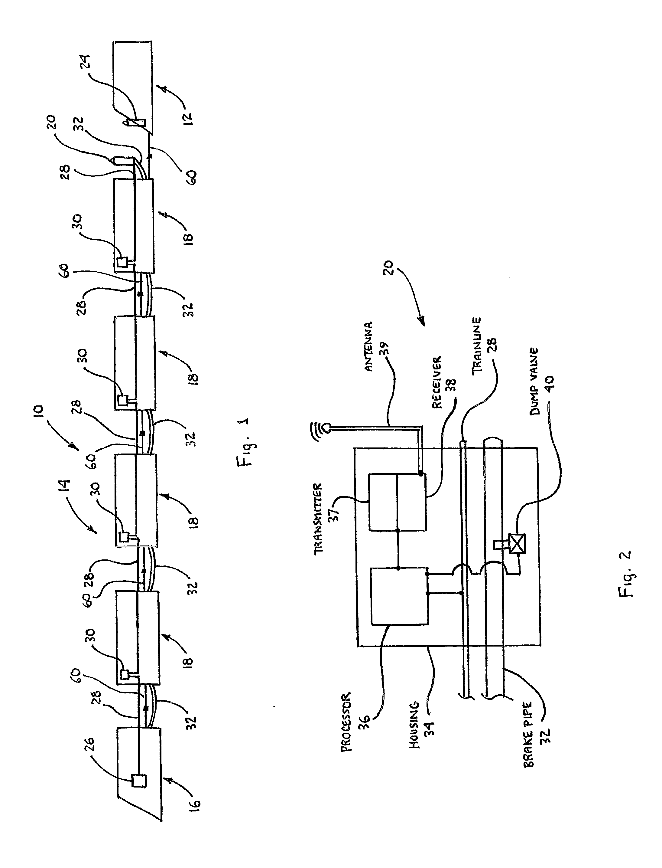
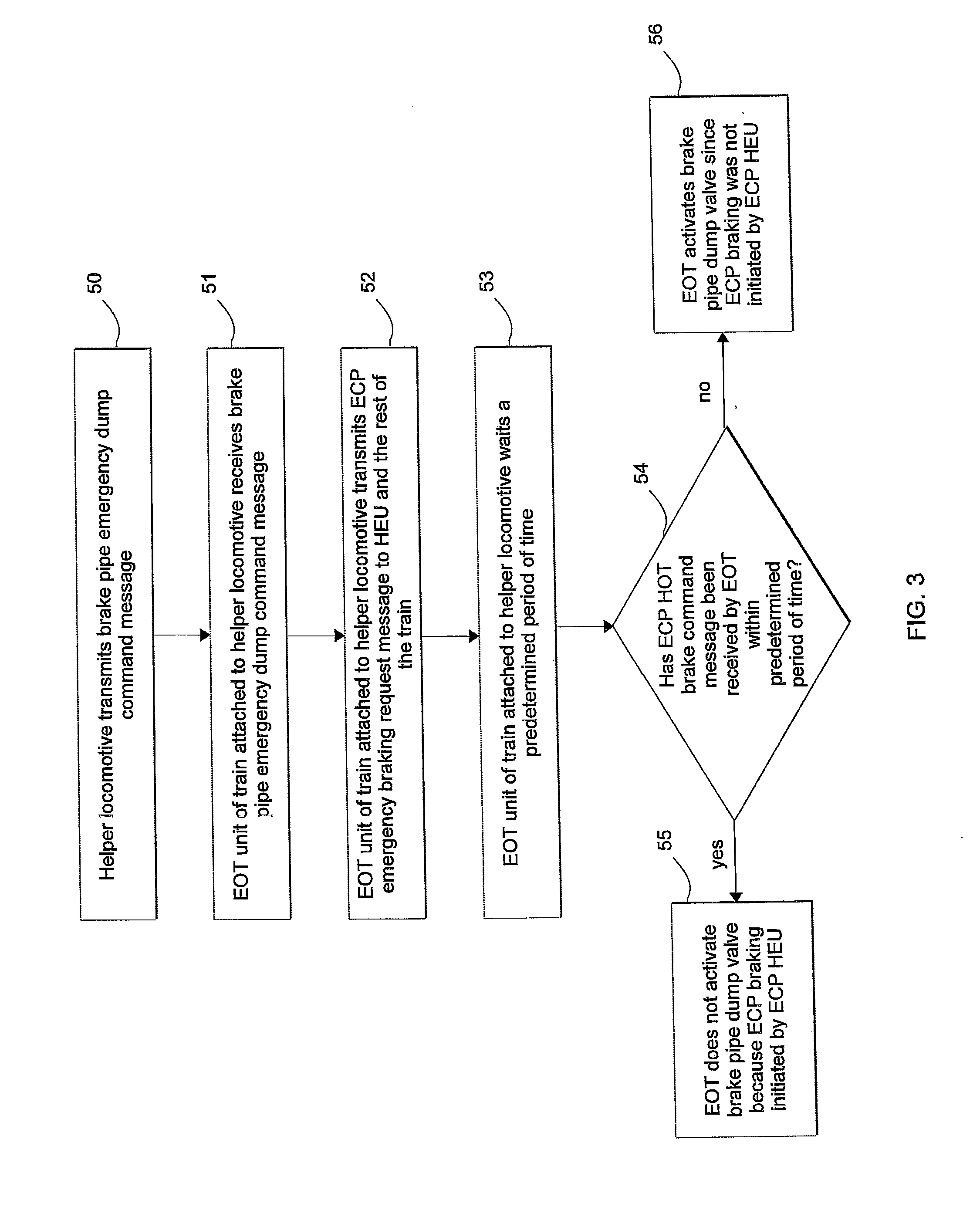
The patent describes a method and system for improving braking safety and reducing recovery time in an electronically controlled pneumatic (ECP)-equipped train after a brake pipe emergency dump command message is transmitted by a helper locomotive. The method involves receiving the brake pipe emergency dump command message at an end-of-train (EOT) unit associated with the train, transmitting an ECP emergency brake request message to at least one car in the train and the head-end-unit (HEU) of the train, waiting for a predetermined period of time for the HEU to transmit an ECP HOT brake command message, and opening a brake pipe dump valve if the ECP HOT brake command message has not been received within the predetermined period of time. The system includes an EOT radio network, a helper locomotive equipped with a virtual brake pipe connection, an EOT unit, and an HEU. The method and system provide benefits such as faster stopping distance, reduced in-train forces, reduced wear and tear, and minimized down-time.

Problems solved by technology

However, a run over an above-average grade may require additional power in the form of a helper locomotive being attached to the end of the train just before traversing the increased grade.
Both operations expose railroad personnel to risk of serious injury.
This sudden and non-graduated removal of air from the brake pipe increases in-train forces and results in depletion of all air, which requires a lengthy recharging and testing of the entire brake system before the train may continue its travel.

Method used


Image

  • System and Method for Addressing a Pneumatic Emergency in a Helper Locomotive
  • System and Method for Addressing a Pneumatic Emergency in a Helper Locomotive
  • System and Method for Addressing a Pneumatic Emergency in a Helper Locomotive

Examples


Embodiment Construction

[0022]For purposes of the description hereinafter, the terms “end”, “upper”, “lower”, “right”, “left”, “vertical”, “horizontal”, “top”, “bottom”, “lateral”, “longitudinal” and derivatives thereof shall relate to the invention as it is oriented in the drawing figures. However, it is to be understood that the invention may assume various alternative variations and step sequences, except where expressly specified to the contrary. It is also to be understood that the specific devices and processes illustrated in the attached drawings, and described in the following specification, are simply exemplary embodiments of the invention. Hence, specific dimensions and other physical characteristics related to the embodiments disclosed herein are not to be considered as limiting. Further any of the steps, functions, or determinations can be made by any suitable computing arrangement or processor, whether a standalone computer or a programming interface, module, software, firmware, or other code ...


PUM


Abstract

Methods and systems for control and use in connection with an electronically controlled pneumatic (ECP)-equipped train after transmission of a brake pipe emergency dump command message by a helper locomotive associated with the train. These methods and systems are implemented in an effort to improve braking safety and reduce brake system recovery time of a train.

Description

BACKGROUND OF THE INVENTION[0001]1. Field of the Invention[0002]The present invention relates to a system and method for addressing a pneumatic emergency initiated in a helper locomotive and, more particularly, to a system and method of improving braking safety and reducing brake system recovery time in an electronically controlled pneumatic (ECP)-equipped train after transmission of a brake pipe emergency dump command message by the helper locomotive associated with the train.[0003]2. Description of Related Art[0004]The air brake system on a train includes a brake pipe which extends the length of the train. The pressure is maintained in the brake pipe by the lead locomotive except when the engineer in the lead locomotive applies the brakes by releasing air pressure. The drop in air pressure propagates down the brake pipe causing brakes to be applied by the locomotives and all the cars in the train. With the advent of two-way end-of-train (EOT) units, an emergency braking event can ...

Claims


Application Information

Patent Timeline
Patent Type & Authority Applications(United States)
IPC IPC(8): B60T8/17B61H13/00
CPCB60T8/885B60T13/665B60T17/228B60T2270/402
Inventor WOLF, CHARLES L.
Owner WABTEC HLDG CORP
Learn More