Clamping mechanism with easy assembly and antenna device therewith
- Summary
- Abstract
- Description
- Claims
- Application Information
AI Technical Summary
Benefits of technology
Problems solved by technology
Method used
Image
Examples
Embodiment Construction
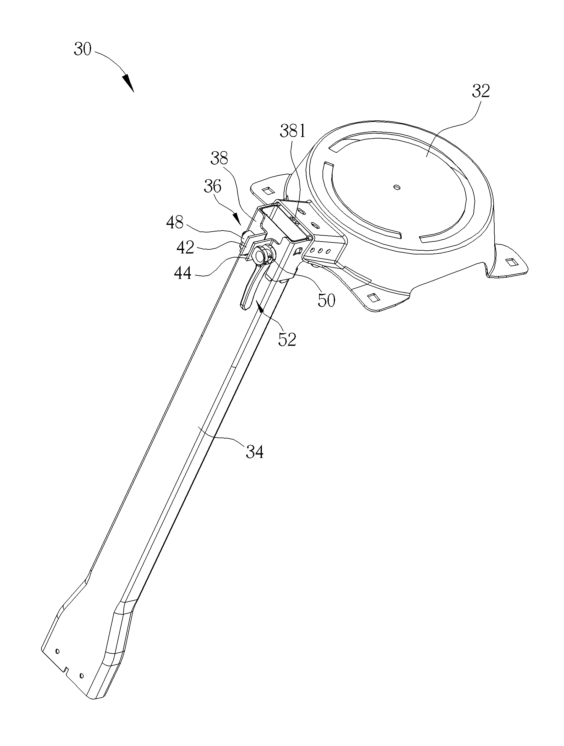
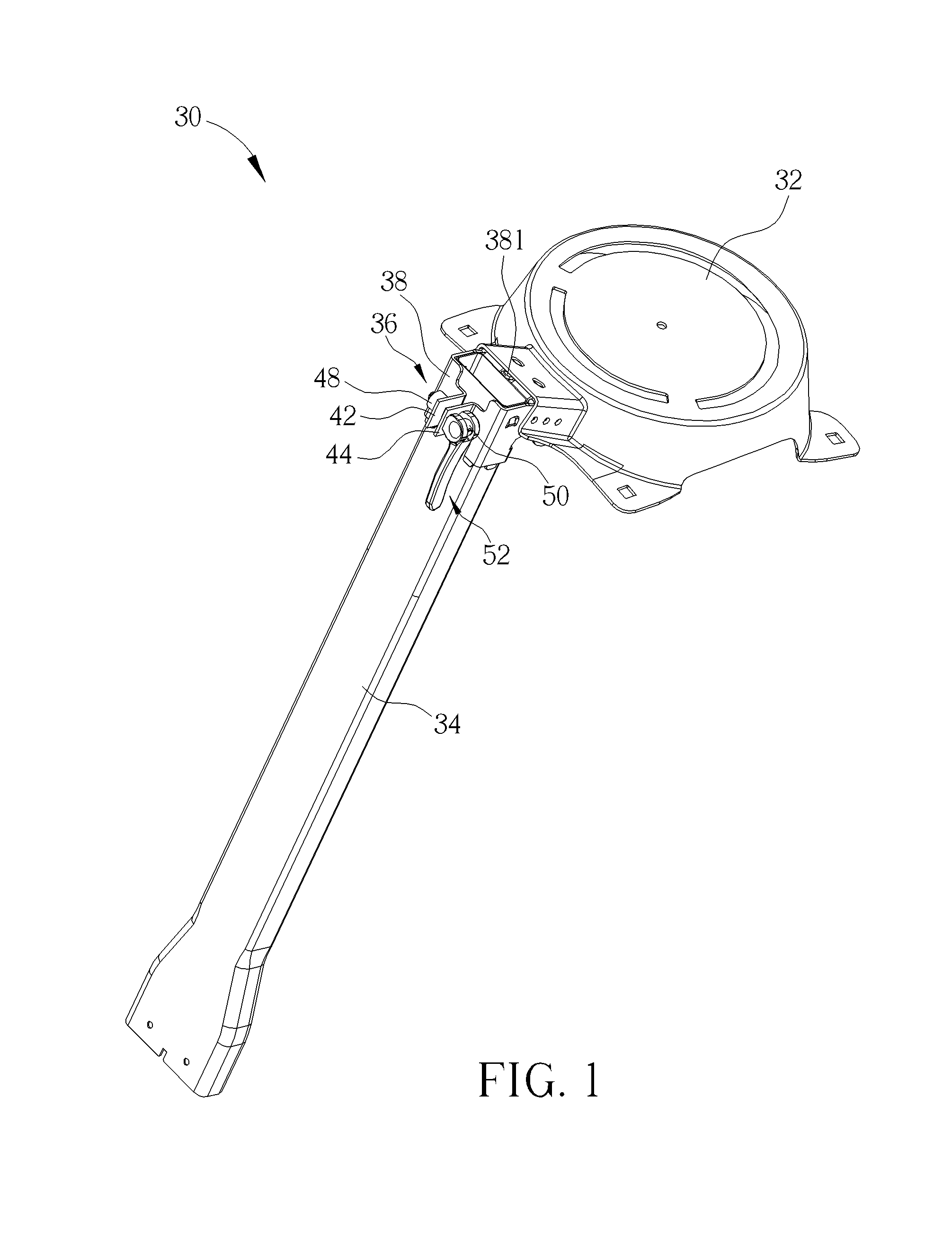
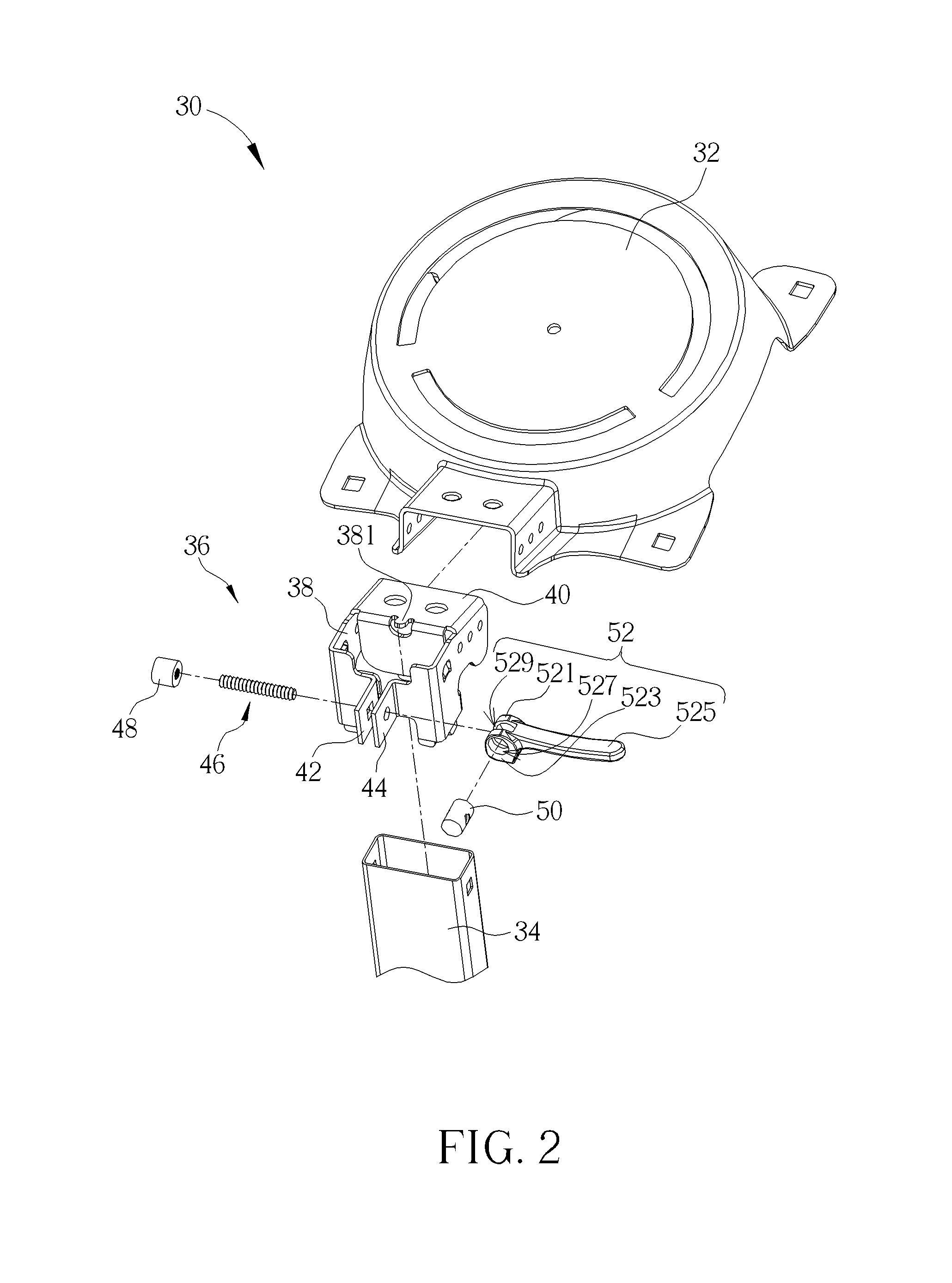
[0033]Please refer to FIG. 1. FIG. 1 is a schematic diagram of an antenna device 30 according to a first embodiment of the present invention. As shown in FIG. 1, the antenna device 30 includes a holder 32, a supporting tube 34 and a clamping mechanism 36. The supporting tube 34 is used for supporting the holder 32. In this embodiment, the supporting tube 34 is a satellite antenna holder, and the holder 32 is used for holding a satellite antenna disk, not shown in figures. Furthermore, the clamping mechanism 36 is used for fixing the holder 32 and the supporting tube 34, such that the satellite antenna disk is disposed on the supporting tube 34 stably by utilizing the holder 32. In such a manner, the satellite antenna disk can be disposed on a fixing plane, such as a ground, for receiving satellite signals. It should be noticed that implementation of the clamping mechanism 36 is not limited to those mentioned in this embodiment. For example, the clamping mechanism 36 can be used for ...
PUM
 Abstract
Description
Claims
Application Information
 - R&D
- Intellectual Property
- Life Sciences
- Materials
- Tech Scout
- Unparalleled Data Quality
- Higher Quality Content
- 60% Fewer Hallucinations
Browse by: Latest US Patents, China's latest patents, Technical Efficacy Thesaurus, Application Domain, Technology Topic, Popular Technical Reports.
© 2025 PatSnap. All rights reserved.Legal|Privacy policy|Modern Slavery Act Transparency Statement|Sitemap|About US| Contact US: help@patsnap.com


