[0022] It is an
advantage of the present invention that the
assembly process of an electro-acoustic transducer becomes significantly easier, because the support member can be used to
handle and centre the surround for further
processing. The support member can either form an integrated part of the
assembly, or it can be a “dummy” support, which will be
cut away shortly after the mounting of the surround to a piston part and / or the mounting of the finalized diaphragm to a basket of an electro-acoustic transducer.
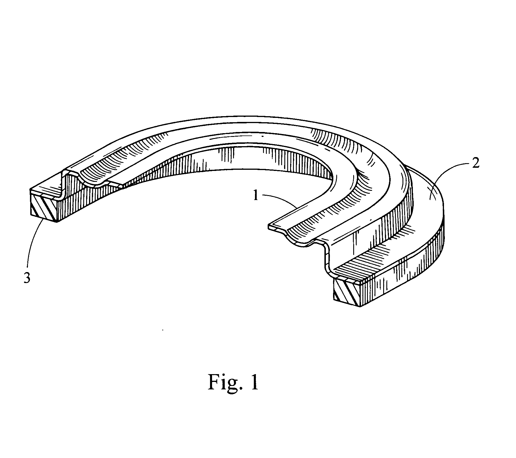
[0023] In case the mechanical support member is integrated with the outer portion of the of the suspension member the outer portion and the support member may be fabricated from the same material, and fabricated in the same manufacturing process, such as an
injection moulding process. In case the support member is of a different material than the outer portion of the surround, the support member may be fabricated separately and attached to the outer portion of the surround at an appropriate stage in the production process. The attaching of the outer portion of the suspension member to the support member may be provided using gluing,
welding, heating or other suitable techniques.
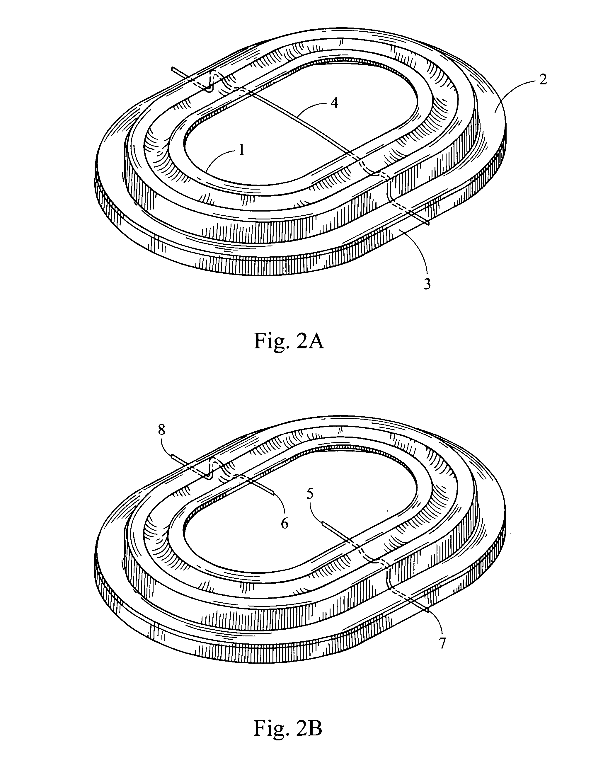
[0024] The flexible member may comprise at least one electrically conducting element adapted to transport electrical signals across the suspension member, for example, signals between one or more circuits arranged on the outer portion side of the suspension member and one or more circuits arranged on the piston. Such circuits may be circuits, such as ASICs, for
signal processing, a circuit to be at least partly positioned and operated in an air gap in an associated
magnetic circuit, etc. The signals to be transported across the surround may be power supply signals,
data signal signals, synchronising signals, etc.
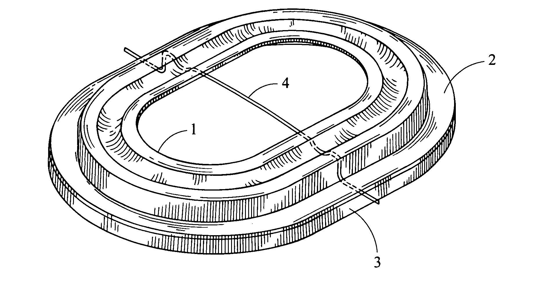
[0025] The at least one electrically conducting element may be at least partly embedded into the flexible member having a first free end accessible at the inner portion and a second free end accessible at the outer portion. Preferably, the at least one electrically conducting element has the form of a thin electrically conducting wire that is fully, except for the first and second free ends, embedded into the surround. The number of wires embedded into the surround can be adjusted depending on the specific application of the diaphragm. Thus, the number of wires may in principle be chosen arbitrarily and the surround may thus comprise 1, 2, 4, 6, 10 or even a higher number of wires embedded into the surround.
[0026] The inner portion of the suspension member may comprise an inner edge adapted to be attached to an associated outer edge of the piston. Thus, according to this embodiment the inner edge of the suspension member forms a through-going opening prior to the piston being attached to the suspension member. Alternatively, the inner portion of the suspension member may comprise a supporting surface adapted to be attached to an associated surface portion of the piston. The supporting surface of the suspension member may comprise an essentially plane surface portion. According to this embodiment the suspension member comprises a supporting surface to which the piston may be glued, welded or by other means attached.
[0027] The surround itself may comprise a material selected from the group consisting of:
silicone, rubber or any combination thereof. However, any soft material with the appropriate mechanical properties may in principle be used. The suspension member may take a substantially circular shape, a substantially oval shape or a rectangular shape. However, other shapes may also be applicable.

