Dual heating system for high speed printing

Inactive Publication Date: 2007-01-25
NAT PEN CORP
View PDF6 Cites 7 Cited by
  • Summary
  • Abstract
  • Description
  • Claims
  • Application Information

AI Technical Summary

Benefits of technology

[0008] Embodiments of the present invention provide a way in which the temperature of roller(s) in printing systems are maintained to facilitate proper image transfer, even at increased speeds. In accordance with the present invention, heat loss from image transfers in the printing system may be compensated by directly applying a secondary source of heat directly to the surface of the silicone rubber coating or covering on the outer surface of the first heater.
[0009] In one embodiment, direct application of heat to the silicone rubber coating of the first heater may be immediately preceding the image transfer to the objec

Problems solved by technology

Because objects that are impressed may have rounded surfaces, small imperfections that may appear in metal roller(s) do not provide a uniform image transfer.
As the number of printing transfers continue, a portion of heat is lost from the system.
However, if too much heat is generated from the heating element, adhesive between the metal roller(s) and the silicone rubber coating may separate and degrade, thereby leading to increased chances of dela

Method used


Image

  • Dual heating system for high speed printing
  • Dual heating system for high speed printing
  • Dual heating system for high speed printing

Examples


Example

[0017] The present invention discloses a dual heating system and apparatus for hot-stamping machines or similar heat transfer mechanisms to achieve high-speed printing of images, such as for example printed color images, on objects having a variety of sizes and shapes, by way of a hot stamping machine and / or a related hot stamping process. The hot stamping machine may be a commercially available machine, for example a machine that is disclosed in U.S. Pat. Nos. 6,151,130 and 6,578,476, which are incorporated by reference herein.

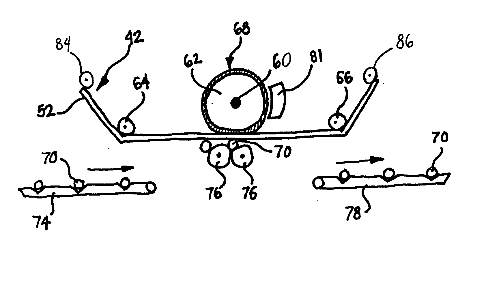
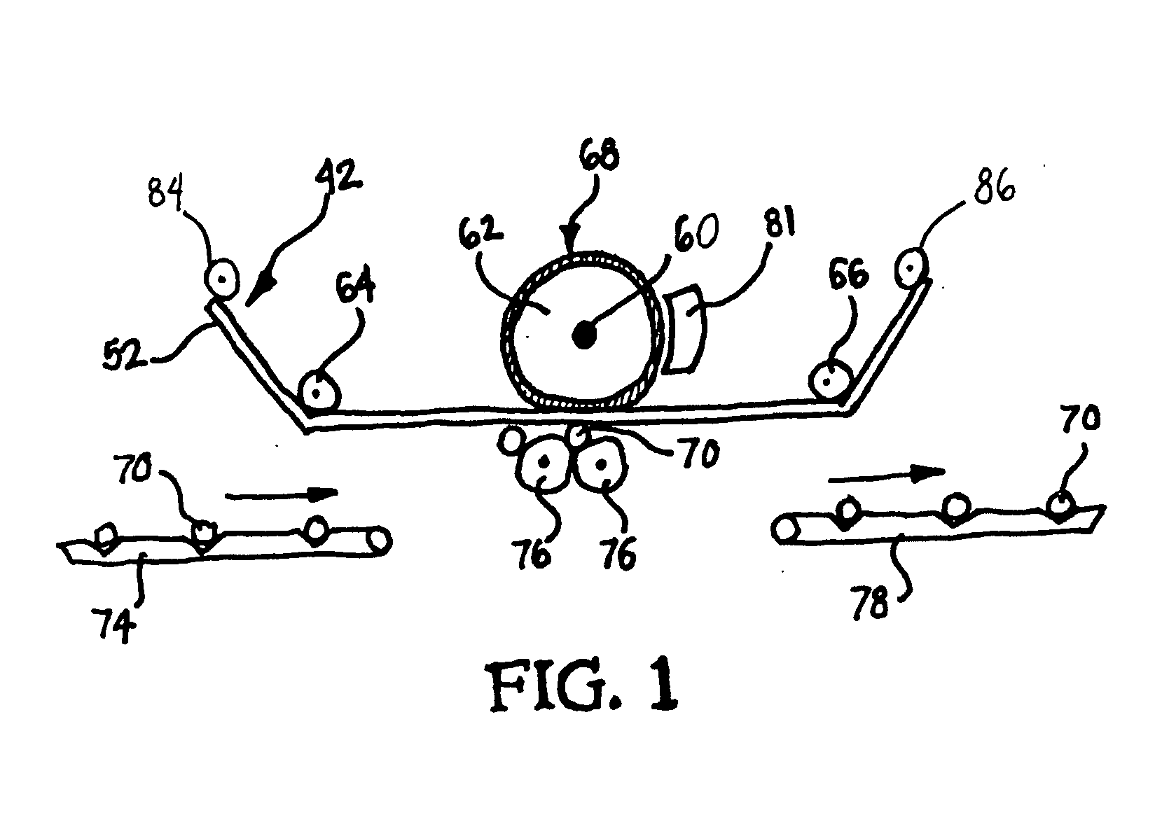
[0018]FIG. 1 shows the basic components of one embodiment of the present invention, respective to the components of a hot stamping machine as described in U.S. Pat. Nos. 6,151,130 and 6,578,476. The interior of the hot stamping machine depicted in FIG. 1 includes a heater 60 that is a metal roller 62, for example, a steel roller. The outer surface of the metal roller 62 has a silicone rubber coating or covering 68. To further explain the embodiments of the d...


PUM


Abstract

A dual heating system and apparatus for high-speed printing is disclosed. A first heater that is a metal roller used in a printing machine. The outer surface of the metal roller may be covered by a silicone rubber coating material to enhance print transfer. This first heater is disposed adjacent to the second side of a print medium. A second heater, located adjacent to the outside of the silicone rubber coating of the first heater, allows supplementary heat to be added to the first heater such that improved printing speeds of heat transfer mechanisms may be achieved.

Description

BACKGROUND [0001] 1. Field of the Invention [0002] Embodiments described herein are directed to a dual heating system for generally any process where images are being heat transferred, such as processes involving decorative hot stamping foils, holographic foils, PMS color foils, silicon die impressed foils, and the like. More particularly, the embodiments are directed to a dual heating system for high speed printing of images, especially printed color images, on objects having a variety of sizes and shapes, by way of a hot stamping machine and / or a related hot stamping process or heat transfer mechanism. [0003] 2. Description of Related Art [0004] Hot stamping machines, such as for example a Harvey roll-on deco machine, preferably a single head model HFR-100 or a double head model HFRO-200, typically contain a single heating element per head. Machines of this type are disclosed in U.S. Pat. No. 4,502,381. These machines were marketed by the Harvey Machine Co. of Nashville, Tenn. Ano...

Claims


Application Information

Patent Timeline
IPC IPC(8): B41L35/14
CPCB41P2219/43B41F16/0086
Inventor LIGUORI, THOMAS A.BATES, KIRBY W.
Owner NAT PEN CORP
Why Eureka
Try Eureka