Sensor positioning for 3D scanning

a technology of 3d scanning and sensor positioning, applied in the field of 3d scanning, can solve the problems of prone to errors, affecting cost, and inertial system not providing a spatial relationship,

Active Publication Date: 2014-03-27
CREAFORM INC
View PDF4 Cites 30 Cited by
  • Summary
  • Abstract
  • Description
  • Claims
  • Application Information

AI Technical Summary

Problems solved by technology

The size, ease of usability, portability, and accuracy are some features that will affect the cost.
Inertial systems do not provide a spatial relationship with respect to a fixed reference; they provide relative motion parameters of the device.
The main limitation of these approaches exploiting the object geometry to calculate the sensor spatial relationship is the object geometry.
Otherwise the positioning will be prone to error.
For example, on a cylinder or a sphere, it is not possible to reliably calculate the six degrees of freedom.
Furthermore, it is difficult to ensure a given level of accuracy which is crucial in many metrology applications.
Moreover, for real-time modeling applications, coarse registration may become intractable for larger or more complex objects.
Nevertheless, relying on these uncontrolled features may not be sufficient to maintain accuracy.
It is also not simple to efficiently take advantage of both modalities using a relative weighting factor.

Method used


Image

  • Sensor positioning for 3D scanning
  • Sensor positioning for 3D scanning
  • Sensor positioning for 3D scanning

Examples


example method steps

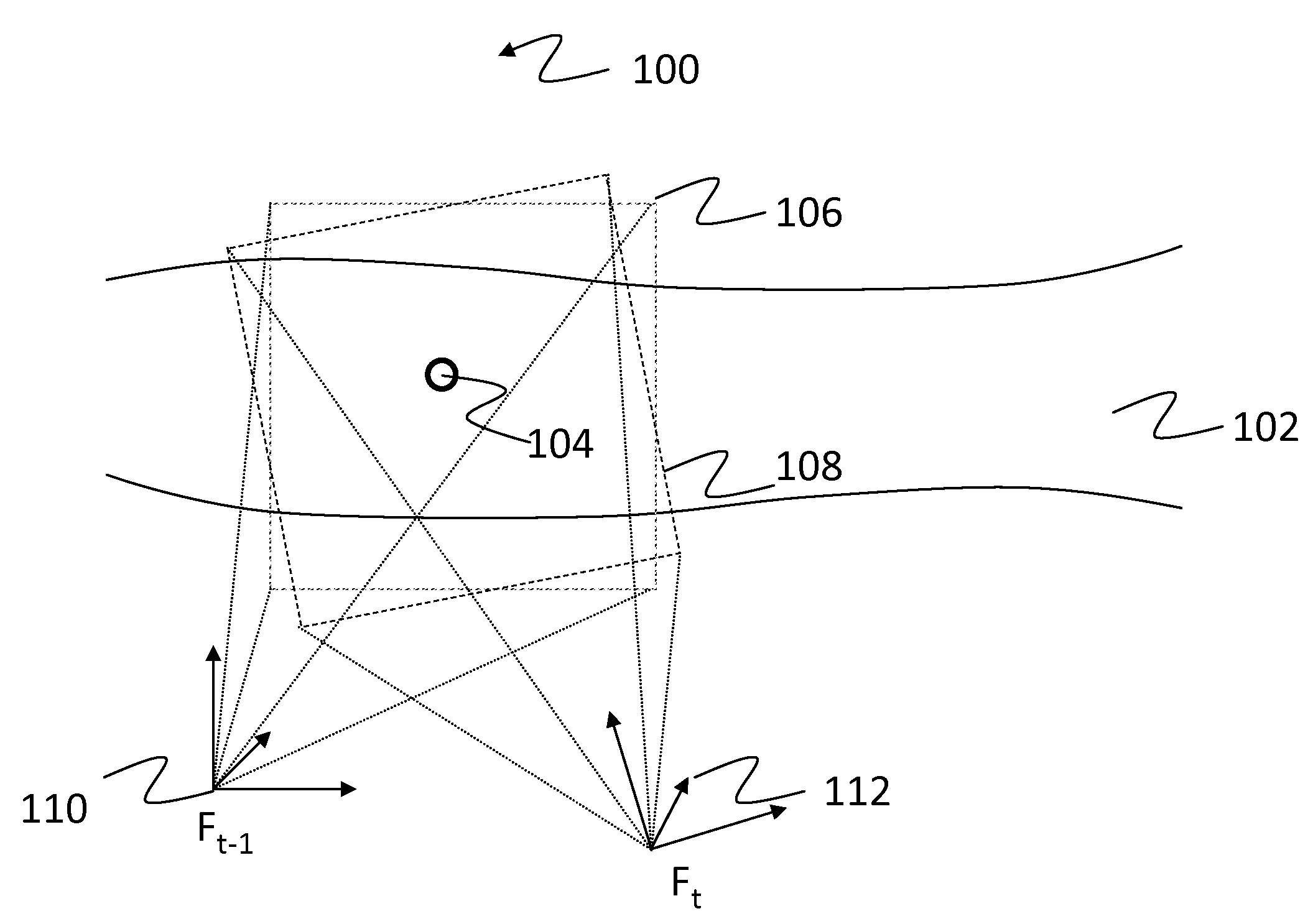
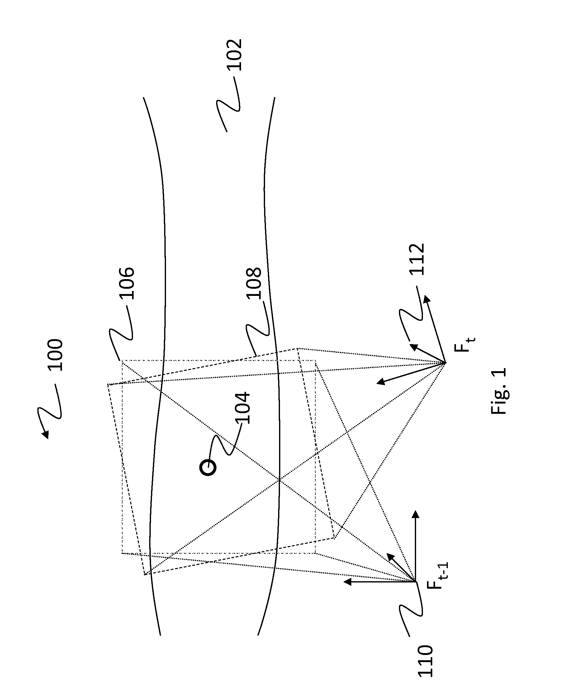
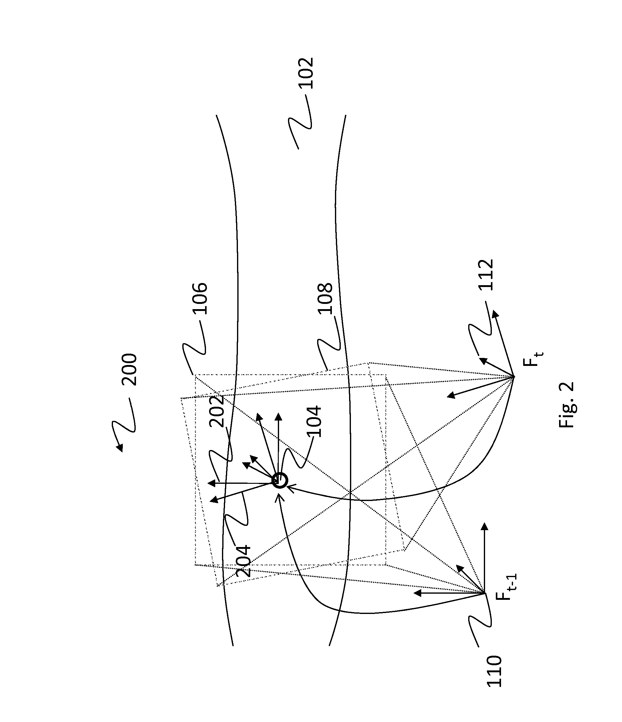
[0092]With reference to FIG. 6, an example method 600 for obtaining a refined pose for a 3D sensor for online 3D modeling of a surface geometry of an object will now be described. The method comprises providing the 3D sensor and a geometry model of at least part of the surface 602; observing a portion of the surface of the object with the 3D sensor 604; measuring an initialization pose for the 3D sensor 606 by positioning device pose measurement (see FIG. 7) and / or predicted pose tracking (see FIG. 8) and / or target observation (see FIG. 9); finding a best fit arrangement of the 3D point measurements in the geometry model using the initialization pose 608 and generating the refined pose for the 3D sensor using the best fit arrangement 610.

[0093]In one embodiment, the refined pose includes at least one parameter of the initialization pose.

[0094]In one embodiment, finding a best fit arrangement includes weighting geometry surface points and target points to find the best fit arrangemen...


PUM


Abstract

A method for obtaining a refined pose for a 3D sensor for online 3D modeling of a surface geometry of an object, the pose encompassing six degrees of freedom (DOF) including three translation parameters and three orientation parameters, the method comprising: providing the 3D sensor, the 3D sensor being adapted to capture 3D point measurements of the surface of the object from a viewpoint; providing a geometry model of at least part of the surface; observing a portion of the surface of the object with the 3D sensor; measuring an initialization pose for the 3D sensor by at least one of positioning device pose measurement, predicted pose tracking and target observation; finding a best fit arrangement of the 3D point measurements in the geometry model using the initialization pose; generating the refined pose for the 3D sensor using the best fit arrangement.

Description

CROSS-REFERENCE TO RELATED APPLICATIONS[0001]This application claims priority under 35USC§119(e) of U.S. provisional patent application No. 61 / 494,075 filed on Jun. 7, 2011, the specification of which is hereby incorporated by reference.TECHNICAL FIELD[0002]The present description generally relates to the field of 3D scanning and modeling of the surface geometry of an object and more particularly to the determination of the sensor pose for 3D scanning.BACKGROUND OF THE ART[0003]A 3D sensor captures 3D points on the surface of an object or a scene. These 3D point measurements are obtained in the coordinate system of the 3D sensor. Since the 3D sensor has a limited field of view, it is generally possible to observe only a section of the surface of the object surface from a single viewpoint. To capture a wider section of the surface, one displaces the 3D sensor, captures 3D points from the new viewpoint, measures and calculates the displacement of the 3D sensor before transforming the ...

Claims


Application Information

Patent Timeline
Patent Type & Authority Applications(United States)
IPC IPC(8): H04N13/02
CPCH04N13/0275G01S5/163G06T2207/10028G06T2207/30204G06T7/80H04N13/275G06T7/75G06T2207/30244
Inventor HEBERT, PATRICKTUBIC, DRAGANGIGNAC, OLIVIERSAINT-PIERRE, ERICROCHETTE, FELIXCARETTE, ALEXANDRE
Owner CREAFORM INC
Why Eureka
Try Eureka