Protection cover and backlight module

Active Publication Date: 2014-03-27
TCL CHINA STAR OPTOELECTRONICS TECH CO LTD
View PDF2 Cites 0 Cited by
  • Summary
  • Abstract
  • Description
  • Claims
  • Application Information

AI Technical Summary

Benefits of technology

[0010]One object of the present invention is to provide a protection cover to timely and fast dissipate the heat therein, improve the heat

Problems solved by technology

These components are often fragile, so they are easy to damage under the case of external disturbance or external touch, and further influence the normal wo

Method used


Image

  • Protection cover and backlight module
  • Protection cover and backlight module

Examples


Example

[0034]The following description of every embodiment with reference to the accompanying drawings is used to exemplify a specific embodiment, which may be carried out in the present invention. Directional terms mentioned in the present invention, such as “top”, “bottom”, “front”, “back”, “left”, “right”, “inner”, “outer”, “side” etc., are only used with reference to the orientation of the accompanying drawings. Therefore, the used directional terms are intended to illustrate, but not to limit, the present invention. In the drawings, the components having similar structures are denoted by the same numerals.

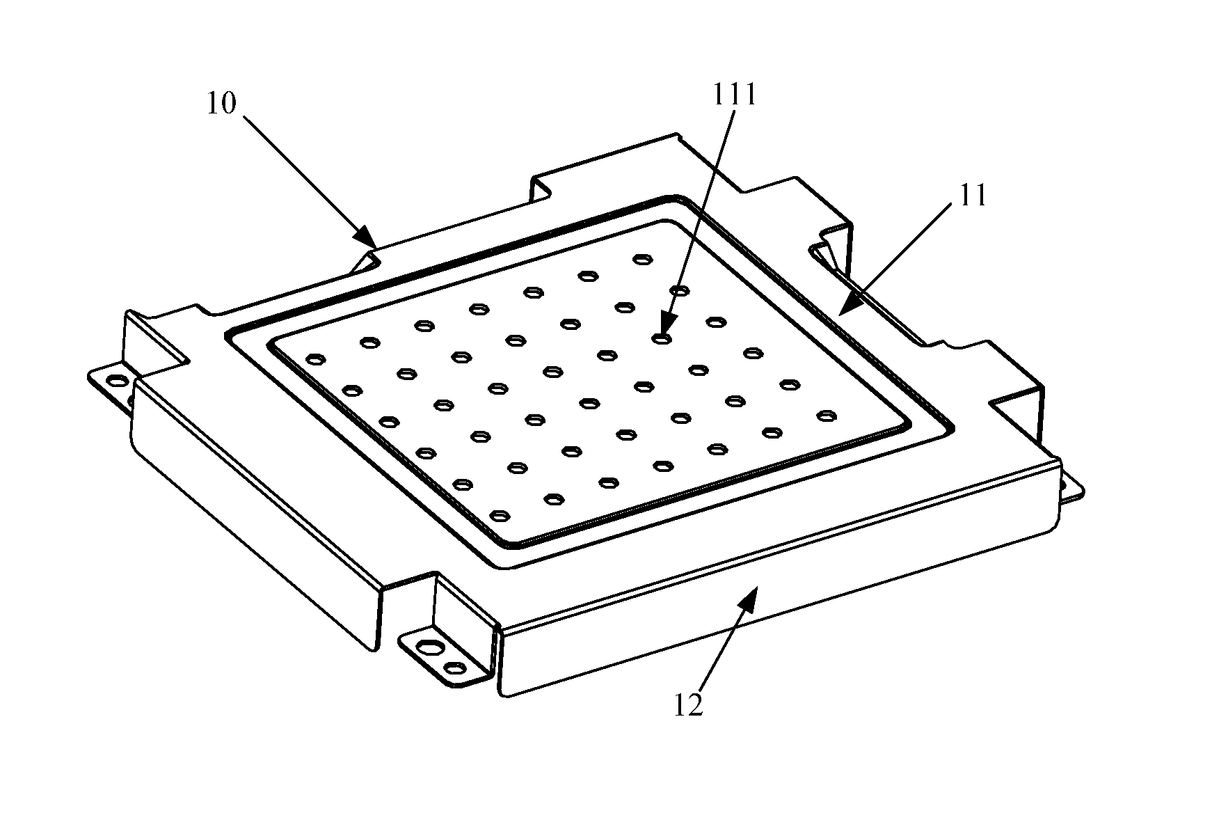
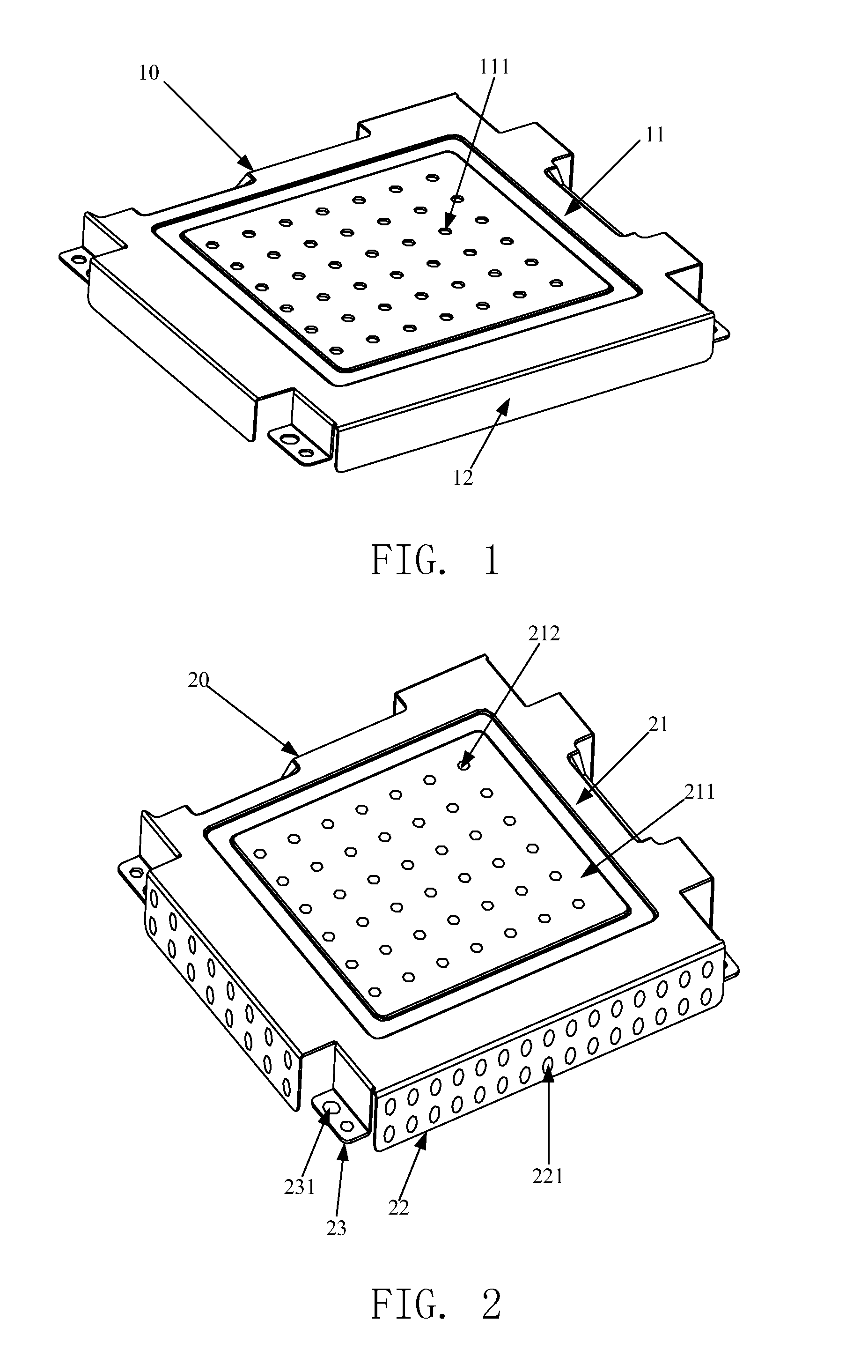
[0035]Please refer to FIG. 2, FIG. 2 is a structure schematic view of a preferred embodiment of a protection cover provided by the present invention.

[0036]The protection cover 20 comprises a cover main body 21. The cover main body 21 disposes a heat dissipation surface 211. Each side edge of the cover main body 21 forms a sidewall 22 protruding with respect to the heat dissipation su...


PUM


Abstract

The present invention provides a protection cover and a backlight module. The protection cover comprises a cover main body. The cover main body includes a heat dissipation surface. Each side edge of the cover main body forms a sidewall protruding with respect to the heat dissipation surface. The heat dissipation surface disposes at least one heat dissipation hole thereon, and the sidewall disposes at least one vent hole thereon. The present invention may timely and fast dissipate the heat in the protection cover, and improve the heat dissipation efficiency.

Description

BACKGROUND OF THE INVENTION[0001]1. Field of the Invention[0002]The present invention relates to a display panel manufacturing technology field, and more particularly to a protection cover and a backlight module.[0003]2. Description of the Prior Art[0004]With the continuous popular of a display panel, the demand for the function of every component of the display panel becomes more and more high.[0005]For a backlight module, the backlight module generally disposes some components, such as a PCB board. These components are often fragile, so they are easy to damage under the case of external disturbance or external touch, and further influence the normal work of the backlight module.[0006]In order to protect these components, the prior art disposes a protection cover to cover the components. For example, please refer to FIG. 1, FIG. 1 is a structure schematic view of the protection cover.[0007]The protection cover 10 comprises a top plate 11 and a side wall 12. Wherein in order to assu...

Claims


Application Information

Patent Timeline
IPC IPC(8): F21V29/00F28F3/02
CPCF28F3/02F21V29/22G02F1/1336G02F1/133314G02F1/133612G02F1/133628G09F13/04
Inventor YU, YA-JUN
Owner TCL CHINA STAR OPTOELECTRONICS TECH CO LTD
Why Eureka
Try Eureka