Transmission interface module and signal transmission method

Active Publication Date: 2020-05-12
ALTEK SEMICON
View PDF7 Cites 0 Cited by
  • Summary
  • Abstract
  • Description
  • Claims
  • Application Information

AI Technical Summary

Benefits of technology

[0009]Therefore, the transmission interface module provided by the present disclosure can greatly reduce power consumption by turning on or turning off components, such as the receiving unit, the tran

Problems solved by technology

However, as requirements for the image are getting higher, so that even though directly transmitting the detecting signal of the image sensor to the processor has become a go-to solution for low-order or mid-range mobile devices, the requirements for high-order images still cannot be met.
However

Method used


Image

  • Transmission interface module and signal transmission method
  • Transmission interface module and signal transmission method
  • Transmission interface module and signal transmission method

Examples


Example

First Embodiment

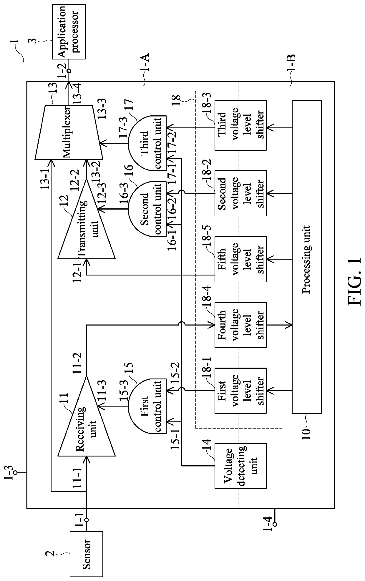
[0023]Referring to FIG. 1, FIG. 1 is a block diagram of a transmission interface module connected to a sensor and an application processor according to an embodiment of the present disclosure.

[0024]In the embodiment, the transmission interface module 1 is electrically connected to a sensor 2 and an application processor 3. The sensor 2 is an image sensor, and the application processor 3 is a processor processing the image signals. An interface between the sensor 2 and the transmission interface module 1 and an interface between the transmission interface module 1 and the application processor 3 are connected with each other through the Mobile Industry Processor Interface D-physical interfaces (MIPI D-PHY).

[0025]The transmission interface module 1 includes a signal input terminal 1-1, a signal output terminal 1-2, an analog power terminal 1-3, and a digital power terminal 1-4. The signal input terminal 1-1 is electrically connected to the sensor 2, and receives a plur...

Example

Second Embodiment

[0059]Referring to FIG. 9, FIG. 9 is a flow chart showing a signal transmission method according to a second embodiment of the present disclosure.

[0060]A signal transmission method is further provided in the embodiment of the present disclosure, which is adapted for the transmission interface module 1 of the first embodiment. The structure and function of the transmission interface module described in the embodiment is the same as described in the previous embodiment, therefore, it is not described herein. In the embodiment, the signal transmission method includes the following steps:

[0061]setting an operation mode of the transmission interface module (step S101)

[0062]adjusting a turn-on state or a turn-off state of an analog power terminal, a digital power terminal, a processing unit, a receiving unit, a transmitting unit, and a multiplexer of the transmission interface module based on an operation mode of the transmission interface module (step S102); and

[0063]tra...


PUM


Abstract

A transmission interface module includes a receiving unit, a transmitting unit, a multiplexer, and a processing unit. An output terminal and a control terminal of the receiving unit are electrically connected to the processing unit. The input terminal and the control terminal of the transmitting unit are electrically connected to the processing unit, and the control terminal of the multiplexer is electrically connected to the processing unit. The transmission interface module respectively adjusts a turn-on state or a turn-off state of the analog power terminal, the digital power terminal, the processing unit, the receiving unit, the transmitting unit, and the multiplexer through a plurality of operation modes to transmit the detecting signals.

Description

CROSS-REFERENCE TO RELATED PATENT APPLICATION[0001]This application claims the benefit of priority to Taiwan Patent Application No. 107142493, filed on Nov. 28, 2018. The entire content of the above identified application is incorporated herein by reference.[0002]Some references, which may include patents, patent applications and various publications, may be cited and discussed in the description of this disclosure. The citation and / or discussion of such references is provided merely to clarify the description of the present disclosure and is not an admission that any such reference is “prior art” to the disclosure described herein. All references cited and discussed in this specification are incorporated herein by reference in their entireties and to the same extent as if each reference was individually incorporated by reference.FIELD OF THE DISCLOSURE[0003]The present disclosure relates to a transmission interface module and a signal transmission method, and more particularly to a...

Claims


Application Information

Patent Timeline
IPC IPC(8): H03M1/12G01R19/25H03K17/00G09G3/36H04B3/54H04N21/63
CPCG01R19/2509H03K17/005G01R19/2503H03M1/1205H03M1/12H04B3/54G09G2330/021G09G3/3677H04N21/631G06F13/382G06F13/4072Y02D10/00
Inventor CHANG, CHING-YEN
Owner ALTEK SEMICON
Why Eureka
Try Eureka