Power module assembly structure

Active Publication Date: 2019-09-19
ZHENGXIN TECH CO LTD
View PDF2 Cites 0 Cited by
  • Summary
  • Abstract
  • Description
  • Claims
  • Application Information

AI Technical Summary

Benefits of technology

[0010]Therefore, due to the change of the structure of the power module assembly structure of the present disclosure, the heat generated by the components is conducted through the metal of low thermal conductivity, and the heat dissipation efficiency can be effectively improved. In addition

Problems solved by technology

The components on the ceramic substrate will generate a great amount of heat due to energization.
Due to the small traces on the ceramic substrate, the heat cannot be quickly conducted through the small traces and the external wires.
Even if the thermal conductivity of the ceramic substrate and the heat sink are relatively high, the thermal grease usually has lower thermal conductivity.
In this way, the heat generated by the components is transmitted to the cerami

Method used


Image

  • Power module assembly structure
  • Power module assembly structure
  • Power module assembly structure

Examples


Example

First Embodiment

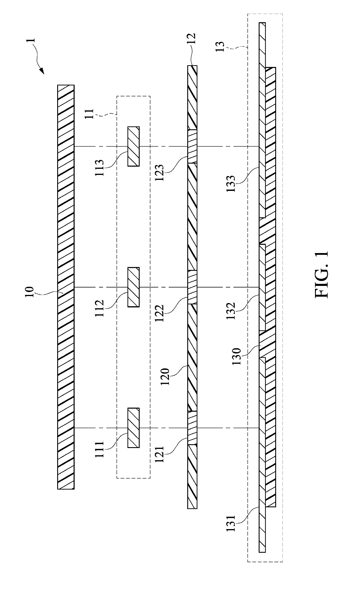
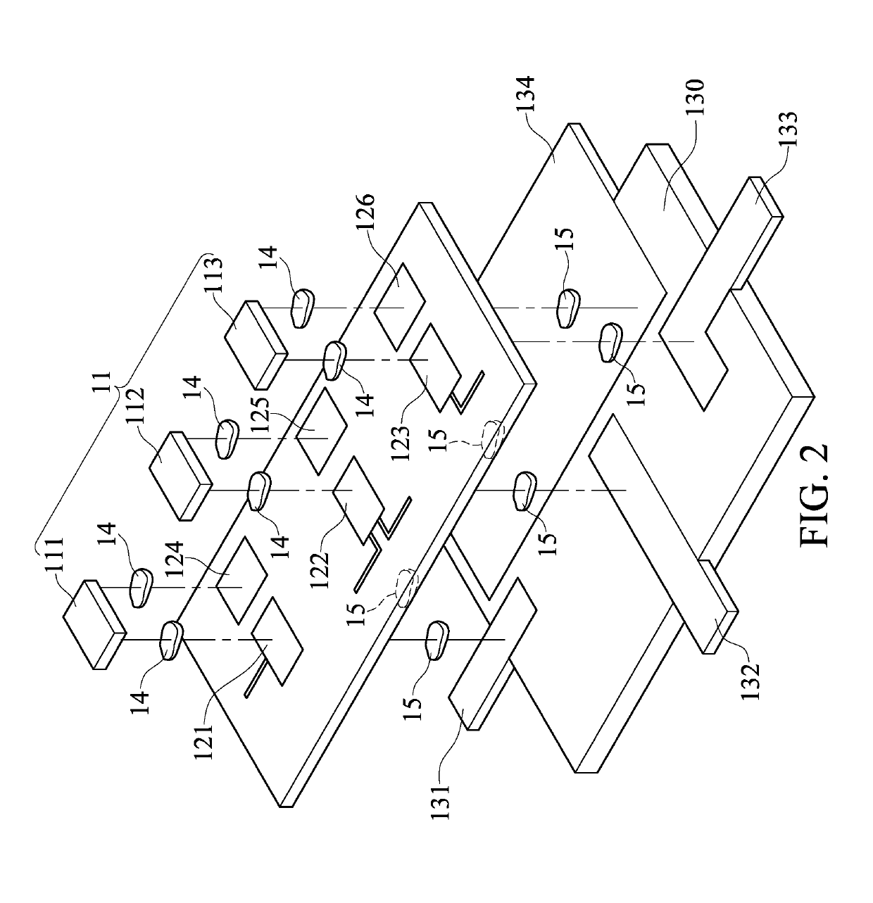
[0018]Referring to FIG. 1 and FIG. 2, FIG. 1 is a schematic cross-sectional view showing a power module assembly structure according to an embodiment of the present disclosure and FIG. 2 is an exploded perspective view showing an assembly structure of a power module according to an embodiment of the present disclosure.

[0019]In the embodiment of the present disclosure, a power module assembly structure 1 is a module or a device for providing a DC voltage or an AC voltage through various power components or power switching components. In the embodiment, the power module assembly structure 1 is not limited to a particular type of power unit or a power switching unit, which is not limited in the present disclosure.

[0020]The power module assembly structure 1 includes an element layer 11, a flexible printed circuit board (flexible PCB) layer 12, and an external wire layer 13. The element layer 11 is disposed on a first side of the flexible printed circuit board layer 12, a...

Example

Second Embodiment

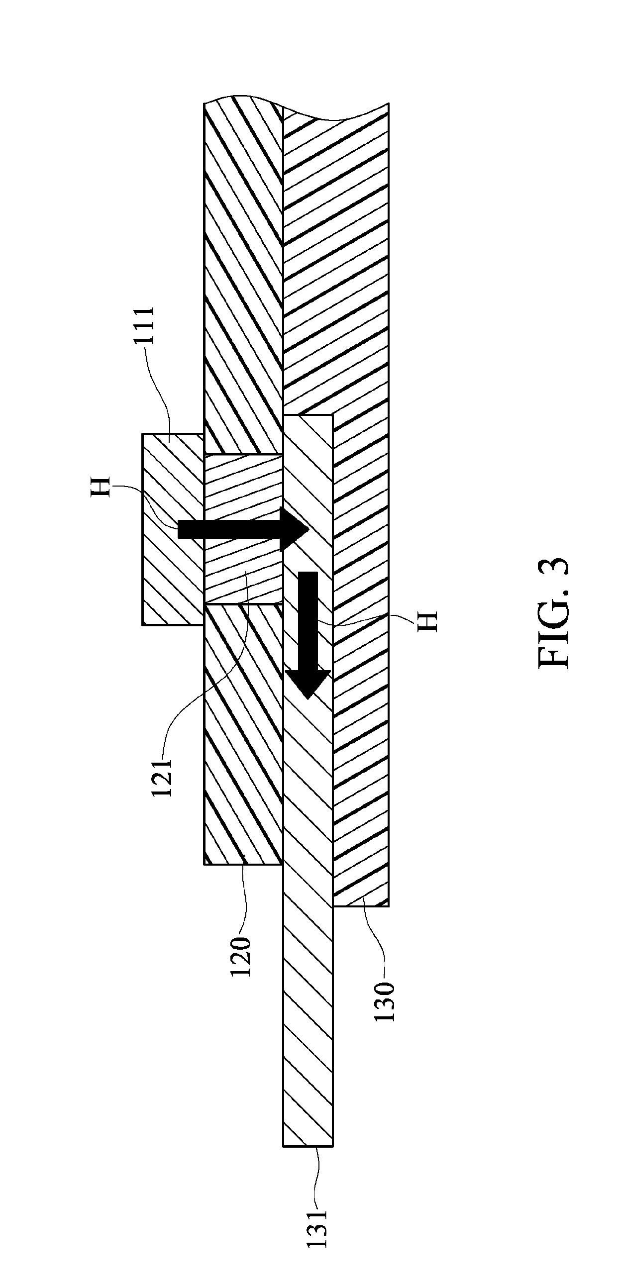
[0036]Referring to FIG. 3, FIG. 3 is a partial schematic diagram of the power module assembly structure of FIG. 1.

[0037]In the power module assembly structure 1, a partially assembled structure is taken as a reference for the description of the heat conduction.

[0038]A heat conduction direction H of the heat generated by the first component 111 is directly transmitted to the first external wire 131 through the first connection material layer 14, the first conductive region 121, and the second connection material layer 15. In the embodiment, the first external wire 131 is a flat-shaped terminal, and the heat transmission efficiency is higher than that of the thin wire-shaped wire. Therefore, the heat can be efficiently conducted to the outside of the power module assembly structure 1.

[0039]Furthermore, in the embodiment, the heat conduction direction H of the heat generated by the first element 111 is conducted through the conductive path of the electric power. In oth...


PUM


Abstract

A power module assembly structure includes an element layer, a flexible printed circuit board layer, and an external wire layer. The element layer includes one component. The flexible printed circuit board layer includes at least one insulating region and at least one conductive region. The external wire layer is disposed on a second side of the flexible printed circuit board layer. The first side and the second side of the flexible printed circuit board layer are two opposite sides, and the external wire layer includes at least one external wire. The at least one external wire is electrically connected to the at least one conductive region of the flexible printed circuit board layer. The heat generated by the one component is directly conducted to the outside of the power module package structure through the at least one conductive region and the at least one external wire.

Description

CROSS-REFERENCE TO RELATED PATENT APPLICATION[0001]This application claims the benefit of priority to Taiwan Patent Application No. 107108635, filed on Mar. 14, 2018. The entire content of the above identified application is incorporated herein by reference.[0002]Some references, which may include patents, patent applications and various publications, may be cited and discussed in the description of this disclosure. The citation and / or discussion of such references is provided merely to clarify the description of the present disclosure and is not an admission that any such reference is “prior art” to the disclosure described herein. All references cited and discussed in this specification are incorporated herein by reference in their entireties and to the same extent as if each reference was individually incorporated by reference.FIELD OF THE DISCLOSURE[0003]The present disclosure relates to a power module assembly structure, and more particularly to a power module assembly structur...

Claims


Application Information

Patent Timeline
IPC IPC(8): H05K1/02H05K1/11H05K1/18
CPCH05K1/0209H05K1/181H05K1/118H05K1/0207H05K2201/0919H05K1/113H05K1/0206
Inventor LIU, TUNG-JUNG
Owner ZHENGXIN TECH CO LTD
Why Eureka
Try Eureka