Photosensitive module

Active Publication Date: 2020-10-22
TDK TAIWAN
View PDF0 Cites 0 Cited by
  • Summary
  • Abstract
  • Description
  • Claims
  • Application Information

AI Technical Summary

Benefits of technology

[0028]The base may be made of a material with high thermal conductivity coefficient to improve the overall heat dissipation effect of the photosensitive module. Furthermore, in some embodiments, the photosensitive module may

Problems solved by technology

However, high-density photosensitiv

Method used


Image

  • Photosensitive module
  • Photosensitive module
  • Photosensitive module

Examples


Example

[0037]In the following detailed description, for the purposes of explanation, numerous specific details and embodiments are set forth in order to provide a thorough understanding of the present disclosure. The specific elements and configurations described in the following detailed description are set forth in order to clearly describe the present disclosure. It will be apparent, however, that the exemplary embodiments set forth herein are used merely for the purpose of illustration, and the inventive concept can be embodied in various forms without being limited to those exemplary embodiments. In addition, the drawings of different embodiments can use like and / or corresponding numerals to denote like and / or corresponding elements in order to clearly describe the present disclosure. However, the use of like and / or corresponding numerals in the drawings of different embodiments does not suggest any correlation between different embodiments. The directional terms, such as “up”, “down”...


PUM


Abstract

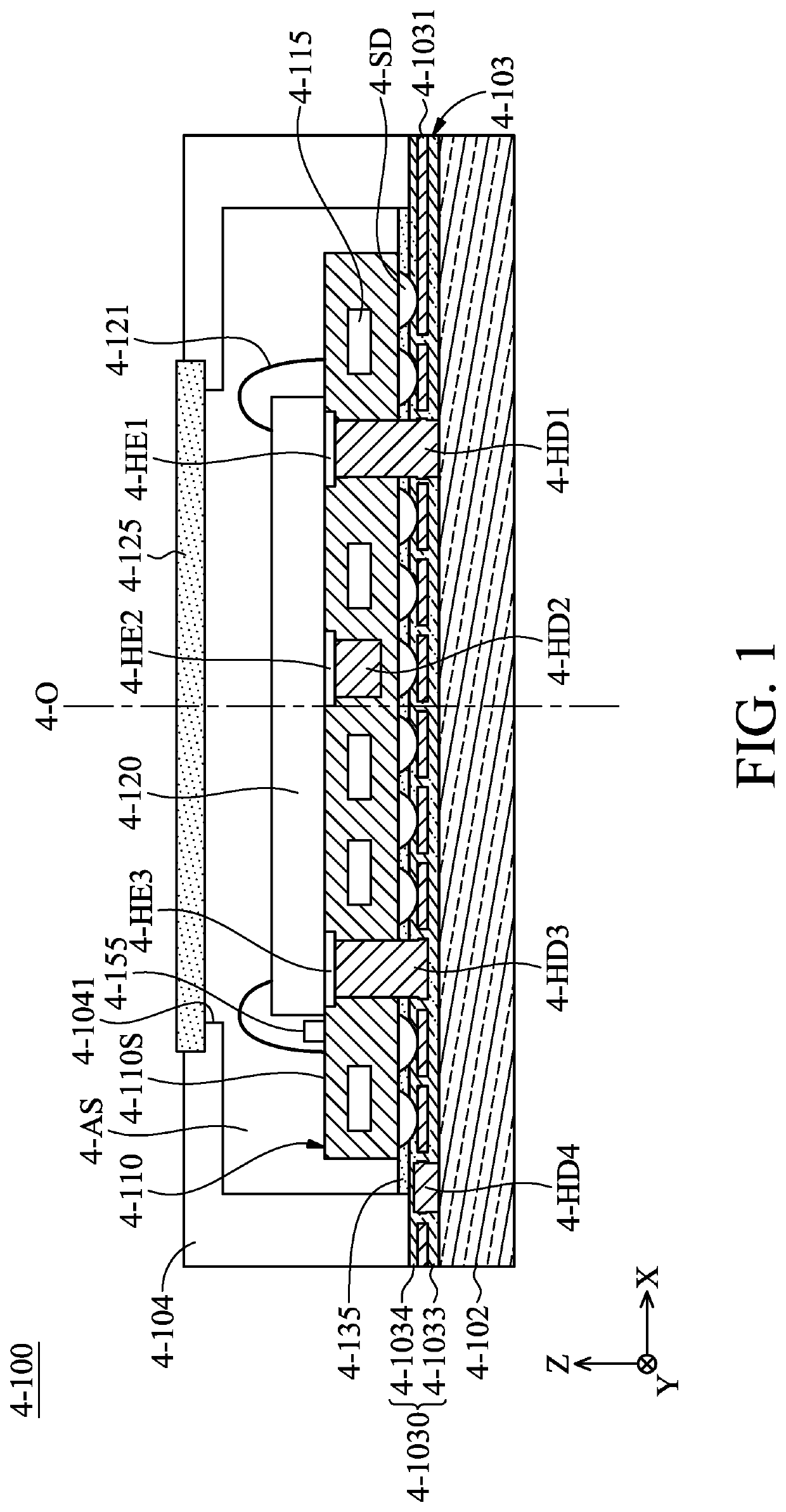
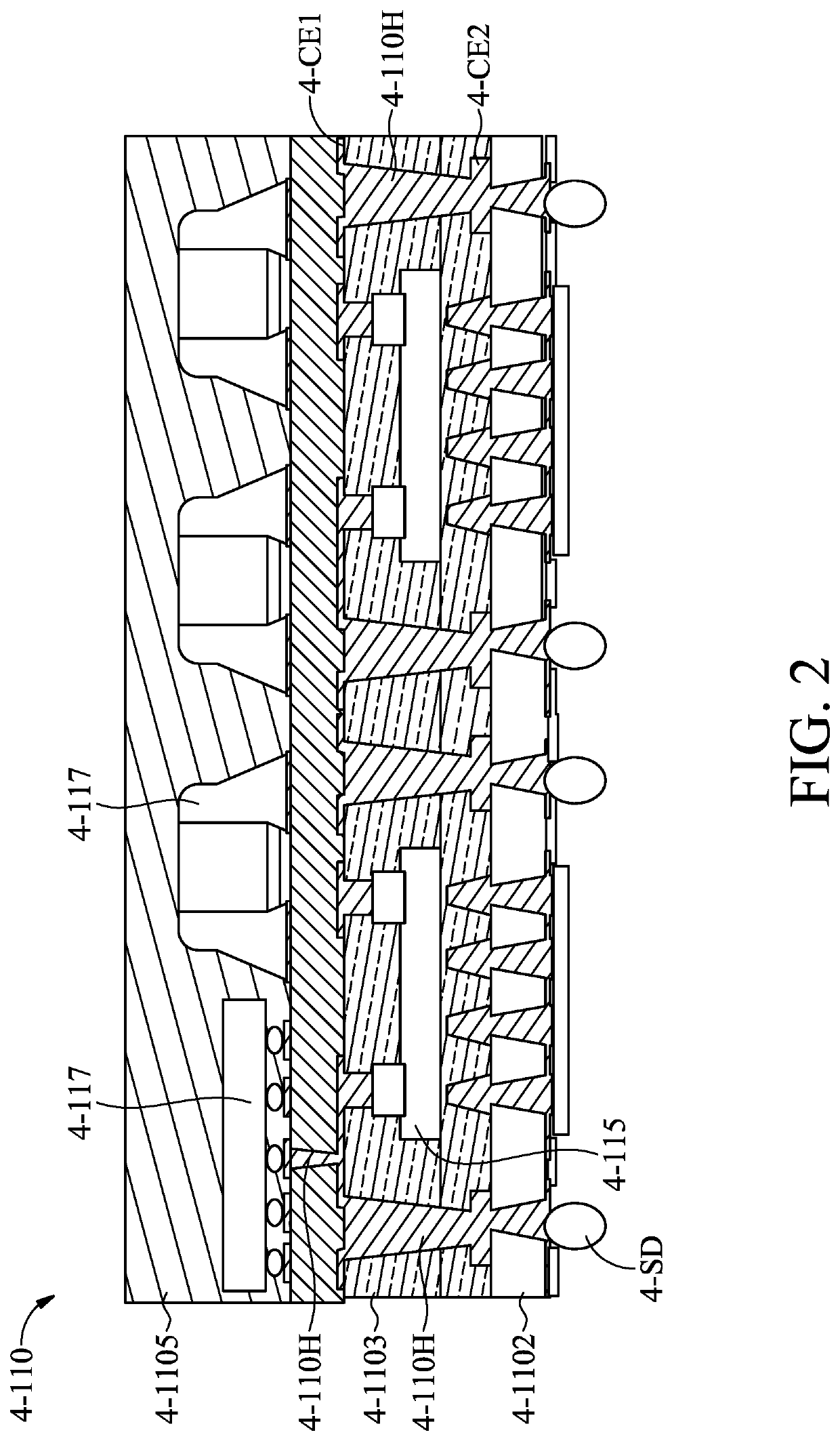
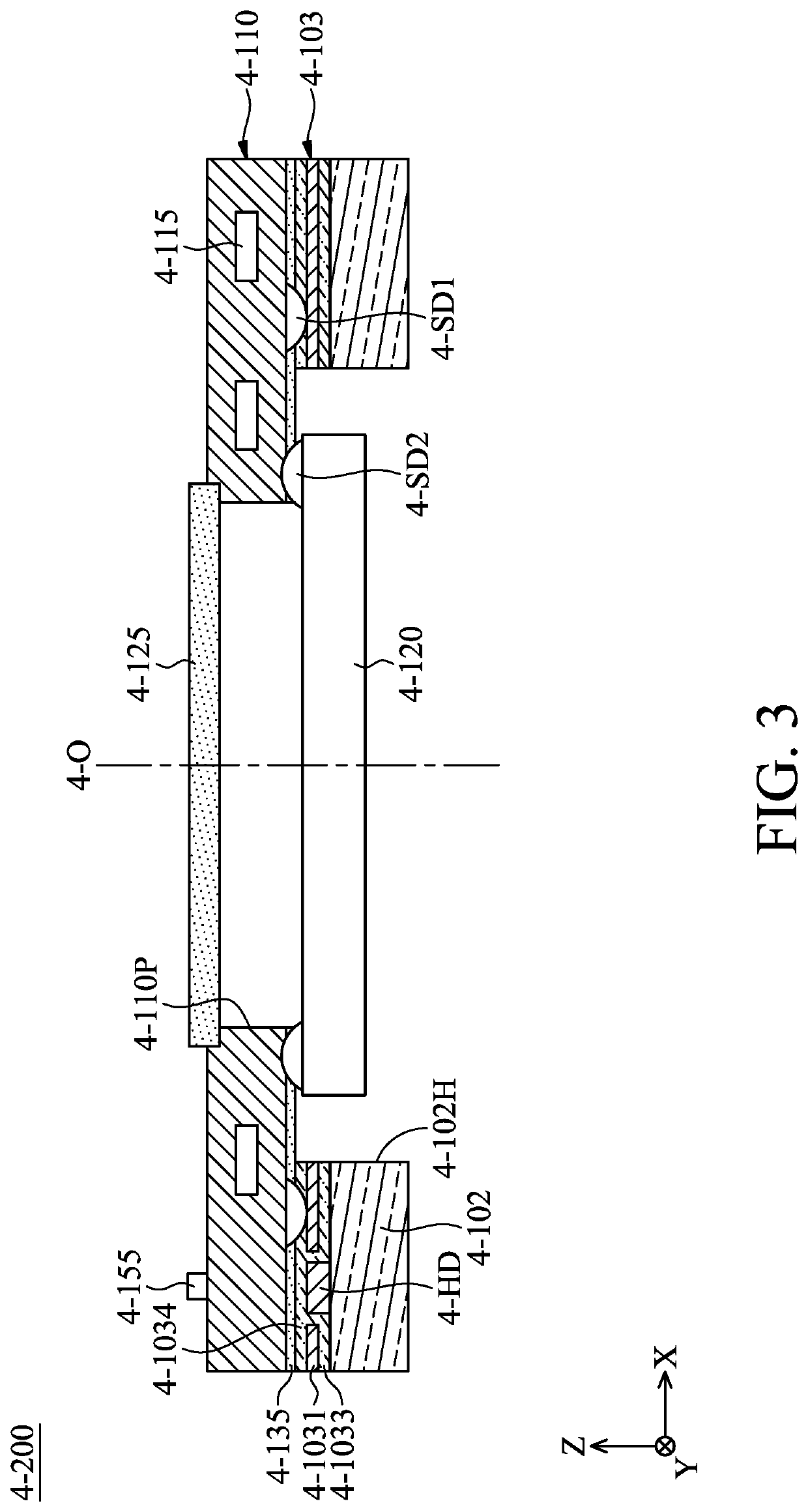
A photosensitive module is provided. The photosensitive module includes a base, an integrated package substrate, and a photosensitive element. The integrated package substrate is connected to the base. The integrated package substrate has a plurality of first electronic components, and the first electronic components are housed inside the integrated package substrate without being exposed to external environment. The photosensitive element is connected to the integrated package substrate, and the photosensitive element is configured to receive a light beam traveling along an optical axis.

Description

CROSS REFERENCE TO RELATED APPLICATIONS[0001]This application claims the benefit of U.S. Provisional Application No. 62 / 836,405, filed Apr. 19, 2019, the entirety of which is incorporated by reference herein.BACKGROUND OF THE DISCLOSUREField of the Disclosure[0002]The present disclosure relates to a photosensitive module, and in particular it relates to a photosensitive module using a semiconductor embedded substrate (SESUB).Description of the Related Art[0003]As technology has developed, many of today's electronic devices (such as smartphones) have a camera or video functionality. Using the camera modules disposed on electronic devices, users can operate their electronic devices to capture photographs and record videos.[0004]Generally, the camera module includes a photosensitive module, and the photosensitive module can be made by different packaging technologies. As semiconductor package manufacturing technology advances, the microelectronic assemblies have become smaller, and the...

Claims


Application Information

Patent Timeline
IPC IPC(8): H01L31/0232H01L31/02H01L31/0236H01L31/113
CPCH01L31/1136H01L31/02327H01L31/02366H01L31/02016H01L27/14625H01L27/14618H01L27/14636H01L2224/48091H01L2224/16225H01L2924/19105H01L2924/00014H01L2924/16195H01L24/48H01L2924/16152H01L2224/48227H01L24/16H01L2924/181H01L2224/16235H01L24/24H01L2224/24225H04N23/54H01L2224/45099H01L2924/00012H01L31/02002H01L31/022466H01L31/024G03B5/00G03B5/02G03B5/04G02B7/1821H02K11/21G02B7/09G02B27/646G03B13/36G03B2205/0007G03B2205/0069H02K41/0356G02B7/003G02B7/08G02B13/0045H01L2224/48106H01L2224/48225H04N23/55H04N23/57
Inventor HSU, CHEN-ERSONG, SIN-JHONGWU, CHI-FUWU, HAO-YUFUKAI, TSUTOMUWU, MING-HUNG
Owner TDK TAIWAN
Why Eureka
Try Eureka