Steam trap monitor with diagnostics

a technology of steam trap and monitor, which is applied in the direction of water supply installation, transportation and packaging, service pipe system, etc., can solve the problems of steam trap completely mechanical, leakage or stick, and steam traps that experience very common problems

Active Publication Date: 2014-04-03
ROSEMOUNT INC
View PDF19 Cites 14 Cited by
  • Summary
  • Abstract
  • Description
  • Claims
  • Application Information

AI Technical Summary

Benefits of technology

[0006]A steam trap monitor includes a process variable sensor configured to sense a process variable related to operation of a steam trap. A memory contains information related to a baseline parameter of the process variable. Diagnostic circuitry calculates a current parameter of the process variable sensed by the process variable sensor and compares the current parameter of the process variable with the baseline parameter. Based on the comparison, the diagnostic circuitry responsively provides a diagnostic output based upon the comparison. The baseline and current parameter are based on a time period during which the steam trap is open or closed.

Problems solved by technology

Often, steam traps are completely mechanical.
Steam traps experience very common problems; they often leak or stick in a closed position.
Steam trap leakage is often due to wear of the movable member within the steam trap; deterioration or fouling of the valve(s) can cause a stick closed.
Regardless of the cause, steam trap leakage or sticking is undesirable for a number of reasons.
First, it takes a relatively large amount of energy to heat water into steam.
Thus, a leaking steam trap will waste energy by allowing steam to escape before the energy content therein can be fully utilized.
Further, many condensate removal systems are not designed for continuous pressurization, such as that caused by a steam leak.
Accordingly, the component(s) downstream from a steam trap could be damaged, or otherwise degraded, by a continuous steam leak.
Further, given a large leak, the steam pipe may not be able to supply sufficient steam pressure and flow to achieve its desired purpose.

Method used


Image

  • Steam trap monitor with diagnostics
  • Steam trap monitor with diagnostics
  • Steam trap monitor with diagnostics

Examples


Embodiment Construction

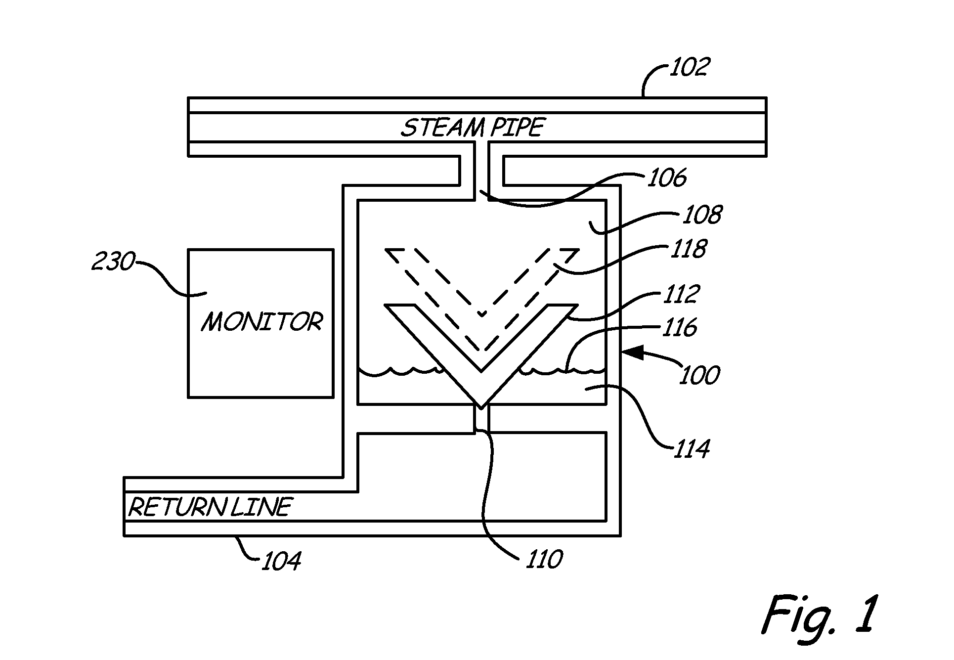
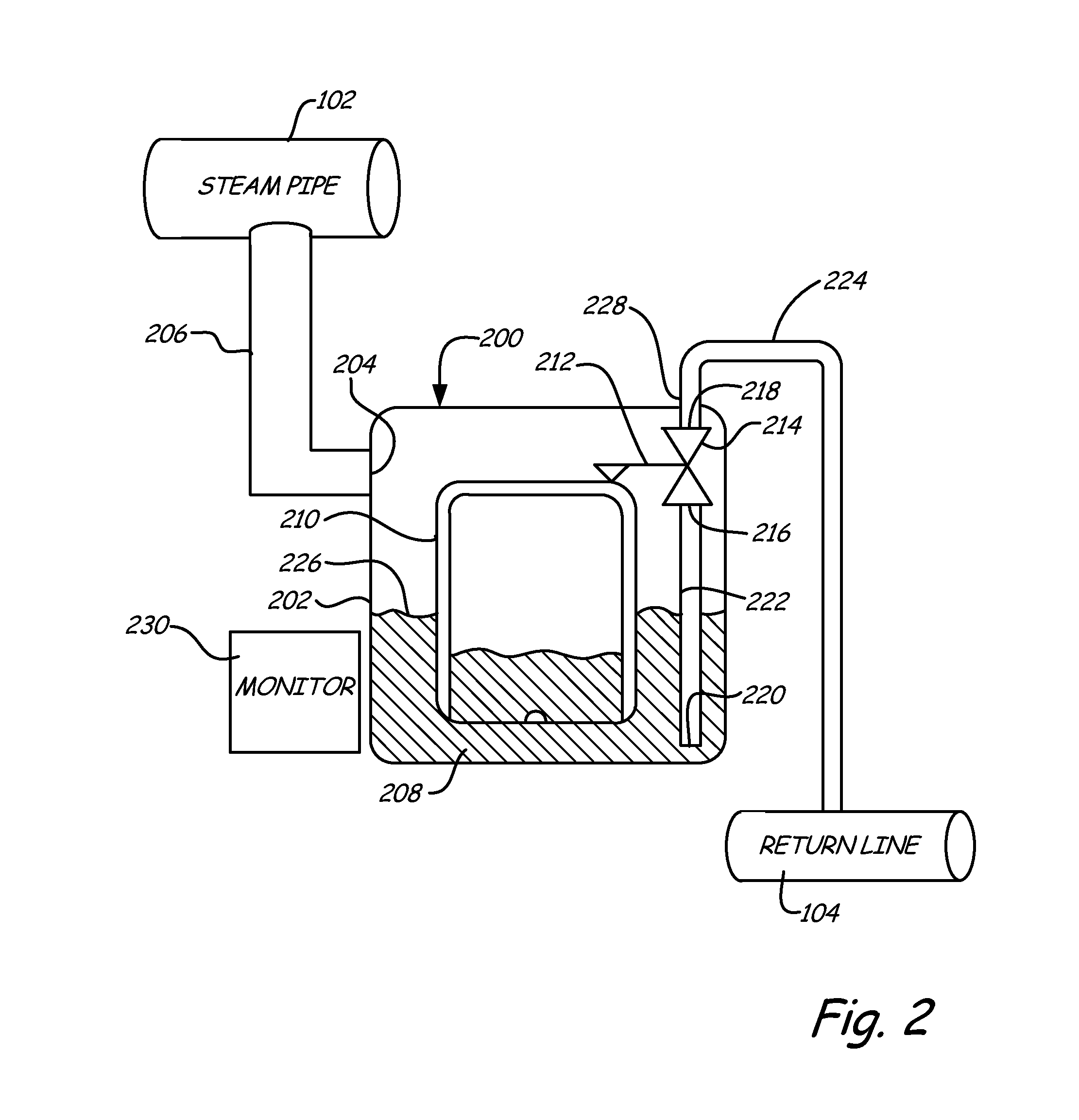
[0012]In the present invention, a steam trap monitor is provided which includes a process variable sensor for use in performing diagnostics on a steam trap. The process variable sensor senses a process variable related to operation of the steam trap. For example, the sensed process variable can be related to the opening and / or closing of the steam trap. Diagnostic circuitry in the steam trap monitor calculates a current parameter of the process variable sensed by the process variable sensor. This is compared with a baseline parameter stored in a memory and used to responsively provide diagnostics.

[0013]Some prior art steam trap monitors simply provide an indication that the trap has completely failed, for example, it is stuck in an open or closed condition. However, it would also be desirable to identify a trap that is in the process of failing prior to its ultimate failure. This allows the steam trap to be replaced at a desired time without unnecessarily shutting down the industria...


PUM


Abstract

A steam trap monitor includes a process variable sensor configured to sense a process variable related to operation of a steam trap. A memory contains information related to a baseline parameter of the process variable. Diagnostic circuitry calculates a current parameter of the process variable sensed by the process variable sensor and compares the current parameter of the process variable with the baseline parameter. Based on the comparison, the diagnostic circuitry responsively provides a diagnostic output based upon the comparison. The baseline and current parameter are based on a time period during which the steam trap is open or closed.

Description

BACKGROUND[0001]The present invention is related to the monitoring of steam traps used in industrial processes. More particularly, the present invention is related to a system and method for detecting a leak or deterioration in a steam trap.[0002]Steam traps are commonly used in many industries to remove unwanted water or condensate from steam lines. In a typical industrial plant, thousands of such devices may be deployed. A steam trap is generally a low technology device that is designed to be relatively inexpensive. Often, steam traps are completely mechanical.[0003]A steam trap is generally designed to allow condensate to escape a pipe in order to maintain efficiency and reduce pipe “knocking.” A typical steam trap may have one or more chambers and a member that is in physical contact with the condensate. As the level of the condensate rises above some threshold, the movable member within the steam trap actuates, or otherwise engages one or more valves to allow the condensate to ...

Claims


Application Information

Patent Timeline
Patent Type & Authority Applications(United States)
IPC IPC(8): F16K37/00
CPCF16K37/00F16T1/48Y10T137/0318Y10T137/8208
Inventor KARSCHNIA, ROBERT J.MOSER, THOMAS M.
Owner ROSEMOUNT INC
Why Eureka
Try Eureka