
Bearingless Reciprocating Slat-Type Conveyor Assemblies

a slat-type conveyor and bearing technology, applied in the direction of conveyors, transportation and packaging, etc., can solve the problems of increasing the wear of the slat, the slats not moving smoothly on the beam, and the power loss is grea

Active Publication Date: 2014-04-03
HALLCO INDS
View PDF1 Cites 3 Cited by
  • Summary
  • Abstract
  • Description
  • Claims
  • Application Information

AI Technical Summary

Benefits of technology

The patent is about a system for holding and moving goods using a reciprocating slat conveyor. The system includes a load-holding compartment, like a tipper trailer, and a lightweight and easily installed conveyor. The conveyor has anchor hooks and subdeck hooks that securely hold the conveyor in place on cross-members that support the conveyor. The installation of the conveyor does not damage the cross-member. The technical effect of this system is that it allows for efficient and secure movement of goods without damaging the equipment used for the movement.

Problems solved by technology

This configuration proved problematic because friction between the slats and the beams resulted in great amounts of power lost to friction and the slats not moving smoothly on the beams.
This was particularly true when the slats became wet and / or worn.
Bearings, however, can be problematic for many reasons including, but not limited to that they can slip or become worn, they require a large amount of labor to install, they require relatively close tolerances for fitting between the subdeck and slats, they allow road debris such as dust and salt to become entrapped between the deck and the bearing thus increasing wear of the slats, they add weight, and they are expensive to replace.
Sometimes it is undesirable to allow the particulate matter to escape the live floor conveyor.
For example, shredded confidential paper can not be allowed to escape for legal reasons.
The filtering of chicken feed, for example, to the ground attracts wild birds which in turn can bring disease to flocks of young chickens and other fowl.
One problem with this conveyor is that large particles can collect in the channel and remain in the channel after the load has been unloaded.
When the particles are confidential documents this problem is not tolerable.
When various cargos are being hauled with the same conveyor it is undesirable to mix the cargos.
Another problem is that the position of the slat on the guide beam is not very stable.
The wide slat is supported only along the length of its center and, therefore, any heavy object sitting offset on the slat can cause the slat to tip on its side and cause uneven wear.
Also, there is little to prevent material from entering the sliding contact area between the bearing and the slat.
When particles enter this joint they reduce the effectiveness of the bearing and cause premature wear.
However, if the seals fail or are not installed properly, there may be at least some places where particulate matter can escape from the conveyor system.
The increased friction also occasionally causes the bearing to slide off the bearing posts.

Method used


Image

  • Bearingless Reciprocating Slat-Type Conveyor Assemblies
  • Bearingless Reciprocating Slat-Type Conveyor Assemblies
  • Bearingless Reciprocating Slat-Type Conveyor Assemblies

Examples


Embodiment Construction

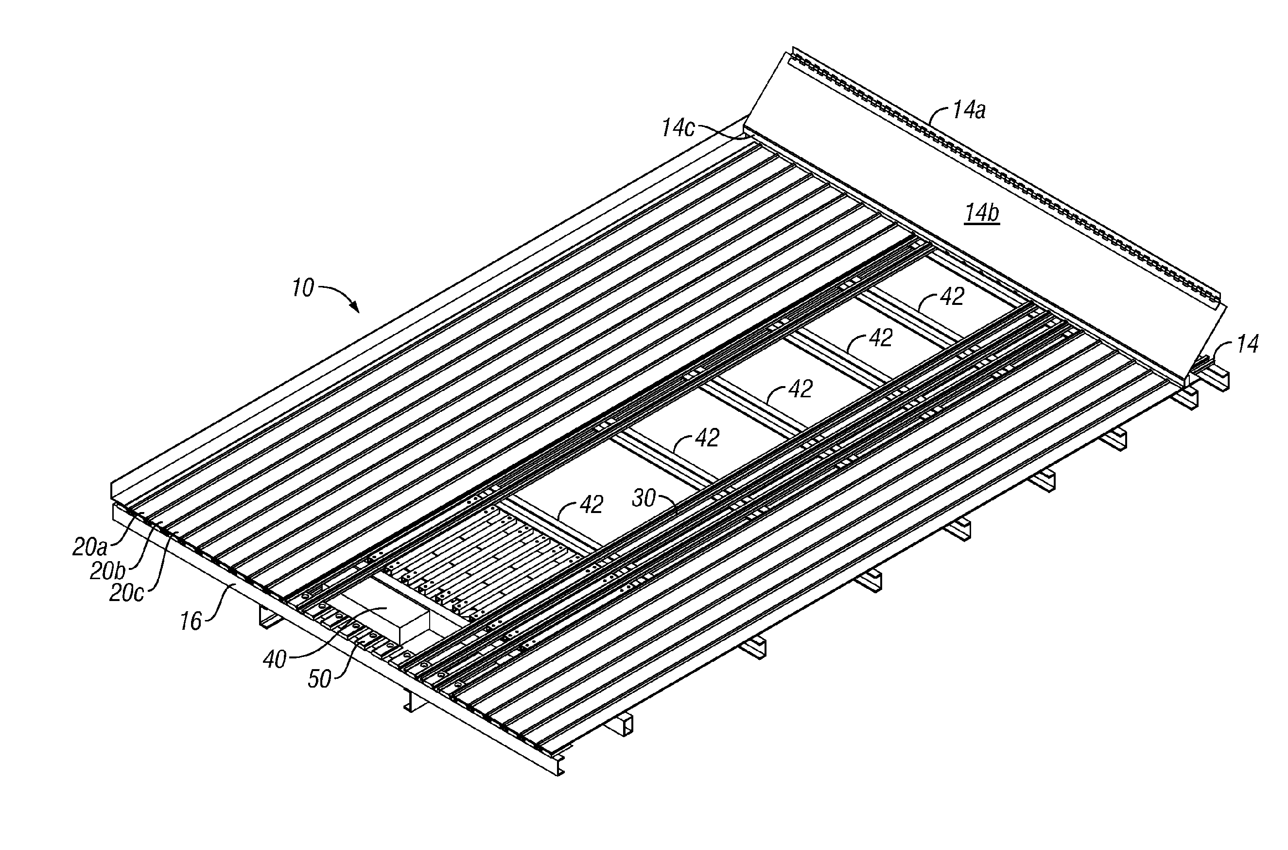
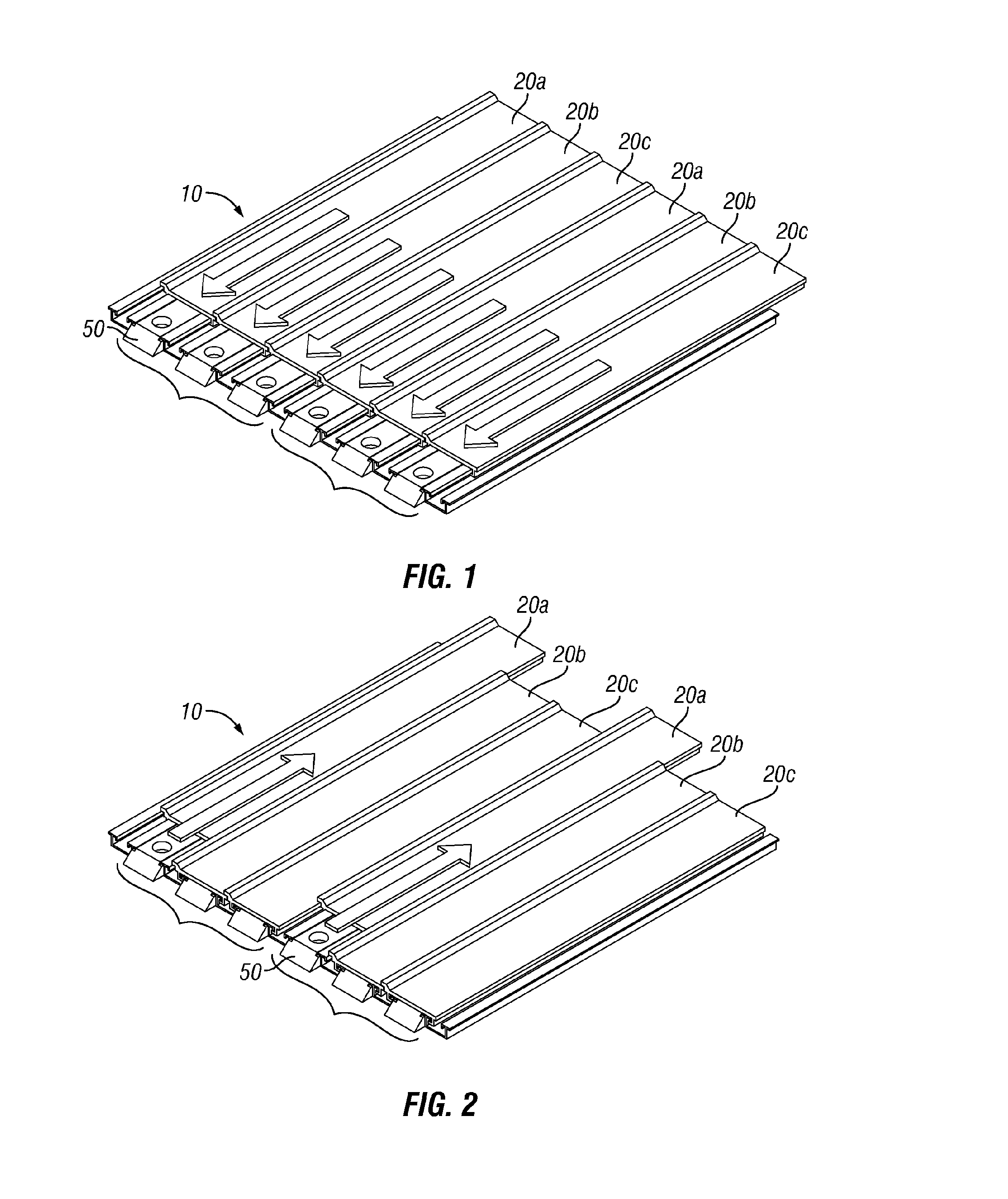
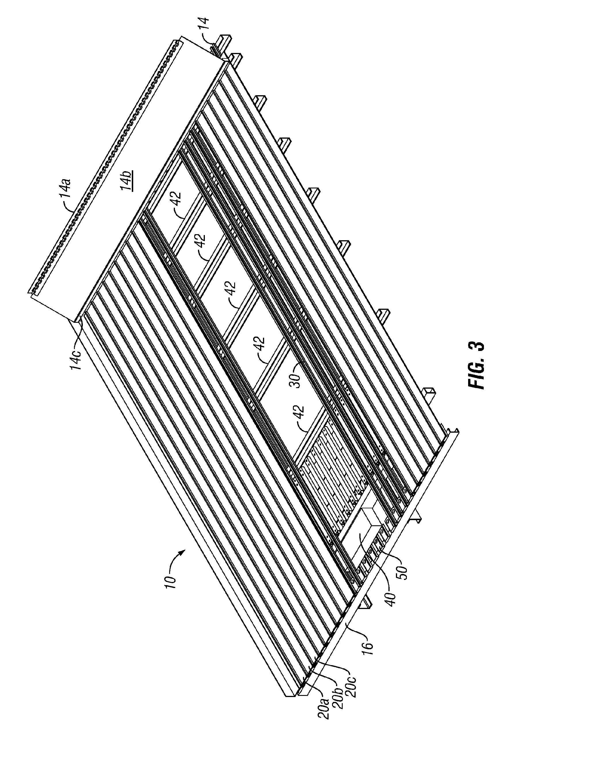
[0080]FIGS. 1-13 are generally directed to the basic concepts of a reciprocating conveyor and / or features of a double-sealed, bearingless, reciprocating conveyor with slat-supporting guide trough subdecks. FIGS. 14-16 and 37-42 are directed to tipper retrofit bearingless reciprocating slat-type conveyor assemblies. FIGS. 17-36 are directed to snap together bearingless reciprocating slat-type conveyor assemblies.

[0081]Before describing the double-sealed, bearingless, reciprocating conveyor with slat-supporting guide trough subdecks of the present invention, some of the basic concepts of a reciprocating conveyor are discussed. Please note that the terms and phrases may have additional definitions and / or examples throughout the specification. Where otherwise not specifically defined, words and phrases are given their ordinary meaning in the art. Exemplary embodiments may be better understood with reference to the drawings, but these embodiments are not intended to be of a limiting natu...


PUM


Abstract

A tipper retrofit bearingless reciprocating slat-type conveyor assembly 200 for use in a load-holding compartment including a plurality of elongate hold down strips 220, a plurality of elongate guide trough subdecks 230, and a plurality of longitudinal slats 210 adjacent to and parallel to each other is described herein. Also described herein is a snap together bearingless reciprocating slat conveyor for use in a load-holding compartment (that has at least one cross-member having an overhang) that includes at least one reciprocating slat-type conveyor assembly 300, 400 and at least one elongate slat 310, 410 at least partially supported by at least one subdeck 330, 430. The at least one reciprocating slat-type conveyor assembly preferably includes at least one anchor 320, 420 (having at least one upper anchor subdeck engager 322, 422 and at least one lower anchor cross-member engager 324, 424) and at least one subdeck 330, 430 (having at least one upper subdeck anchor-slat engager 320, 420 and at least one lower subdeck cross-member engager 344, 444).

Description

[0001]The present application is a continuation of Patent Cooperation Treaty (PCT) application No. PCT / US2013 / 031815, filed Mar. 15, 2013; PCT Application No. PCT / US2013 / 031815 is a continuation-in-part of U.S. patent application Ser. No. 13 / 089,307, filed Apr. 18, 2011; U.S. patent application Ser. No. 13 / 089,307 is a continuation-in-part of U.S. patent application Ser. No. 12 / 332,335 (now U.S. Pat. No. 7,926,646), filed Dec. 10, 2008. The present application is also a continuation-in-part of U.S. patent application Ser. No. 13 / 089,307, filed Apr. 18, 2011; U.S. patent application Ser. No. 13 / 089,307 is a continuation-in-part of U.S. patent application Ser. No. 12 / 332,335 (now U.S. Pat. No. 7,926,646), filed Dec. 10, 2008. The present application is based on and claims priority from these applications, the disclosures of which are hereby expressly incorporated herein by reference.BACKGROUND OF INVENTION[0002]This invention relates to bearingless reciprocating slat-type conveyor ass...

Claims


Application Information

Patent Timeline
IPC IPC(8): B65G25/06
CPCB65G25/065
Inventor BERTHELSEN, TIMOTHY M.BYERS, BRADY L.DANIS, GREGORY P.
Owner HALLCO INDS
Learn More