Apparatus for synthetic imaging of an object

a technology of synthetic imaging and apparatus, applied in the field of synthetic imaging, can solve the problems of inability to achieve, introduce additional losses, and inability to easily achieve microwave/millimeter-wave transceivers

Active Publication Date: 2014-04-03
BATTELLE MEMORIAL INST
View PDF26 Cites 55 Cited by
  • Summary
  • Abstract
  • Description
  • Claims
  • Application Information

AI Technical Summary

Benefits of technology

[0019]In another embodiment of the present invention, a method of synthetic imaging of an object is disclosed. The method includes providing a plurality of transmitter elements spaced apart by a first distance in a first column. The method further includes providing a plurality of receiver elements spaced apart by a second distance in a sec

Problems solved by technology

This forces the antennae to be very small, and therefore low-gain, and will frequently cause antenna coupling problems between adjacent or neighboring antennae.
An additional problem is that the microwave/millimeter-wave transceiver must be capable of separating the transmit signal from the receive signal.
This is possible using directional couplers or circulators, however, these introduce additional losses and do not perfectly isolate the weaker received signal from the much stronger transmitted signal.
Additionally, this design allows amplifiers to be placed within the switching network to compensate for switching losses, which is not readily accomplished if each element must act as both a transmitter and a receiver.
This error is simply due to the round-trip path length difference between the path emanating from the mid-point versus the actual round-trip path.
This

Method used


Image

  • Apparatus for synthetic imaging of an object
  • Apparatus for synthetic imaging of an object
  • Apparatus for synthetic imaging of an object

Examples


Embodiment Construction

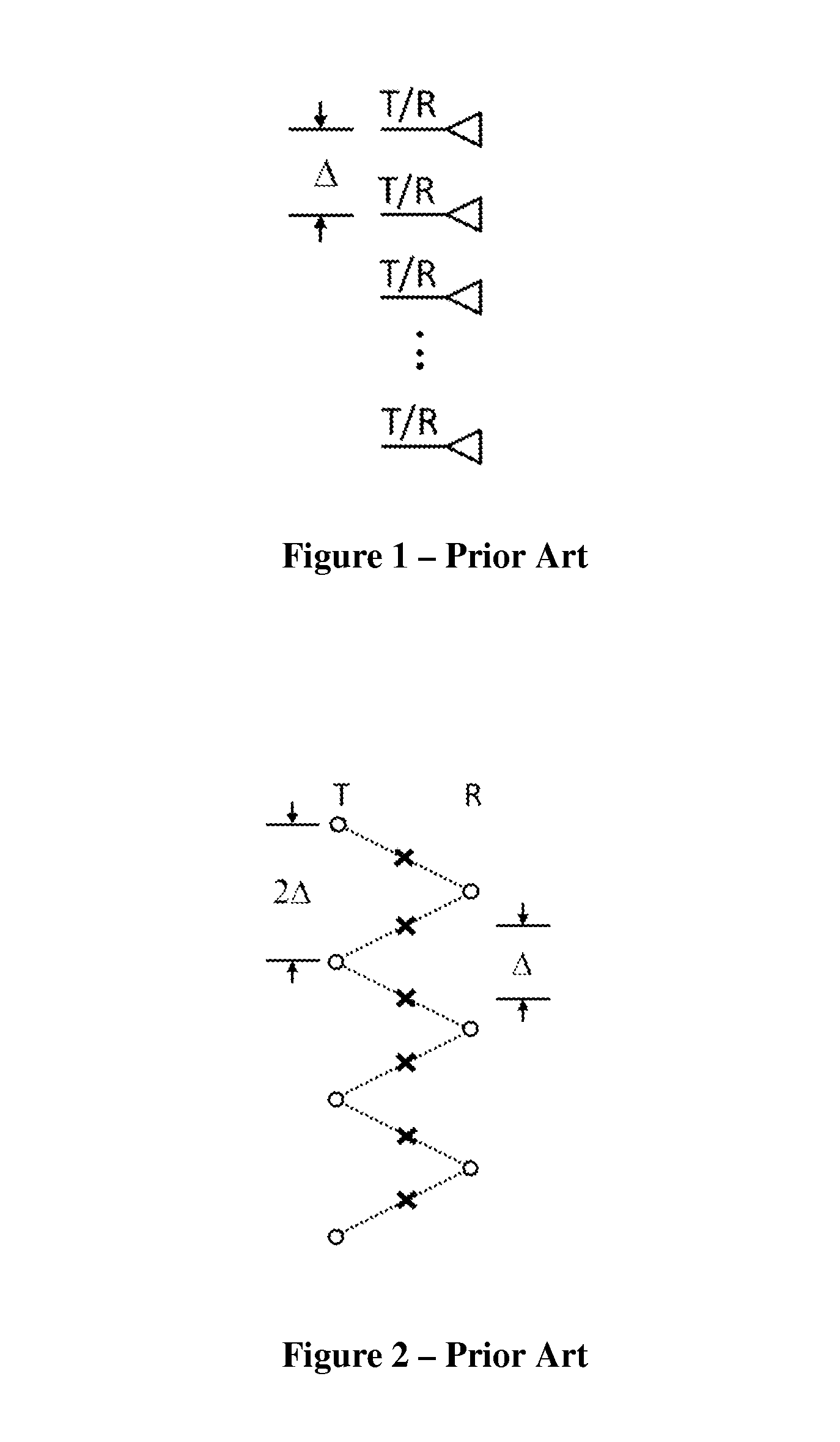
[0044]The present invention is directed to apparatuses for and methods of synthetic imaging of an object. Advantages and benefits of the present invention compared to the prior art include the following. The present invention reduces the number of transmit and receive antennas required to densely sample a linear axis. The present invention also provides a single column of virtual samples. In addition, the present invention maintains dedicated transmitters and receivers, ideally as separate columns of a two column array.

[0045]The present invention allows antennas that may be up to several wavelengths wide in both cross-sectional dimensions. This may require that both transmit and receive arrays are reduced in antenna count.

[0046]The present invention provides uniform spatial effective sampling, which may be needed for low-artifact imaging and Fourier Transform-based image reconstruction. The present invention further provides dense sub-wavelength effective sampling, which may be nece...


PUM


Abstract

An apparatus for synthetic imaging of an object is disclosed. The apparatus includes a plurality of transmitter elements spaced apart by a first distance in a first column and a plurality of receiver elements spaced apart by a second distance in a second column. The first distance and the second distance are different. The plurality of transmitter elements is a non-integer multiple of the plurality of receiver elements, and the plurality of receiver elements is a non-integer multiple of the plurality of transmitter elements.

Description

STATEMENT REGARDING FEDERALLY SPONSORED RESEARCH OR DEVELOPMENT[0001]The invention was made with Government support under Contract DE-AC05-76RLO1830, awarded by the U.S. Department of Energy. The Government has certain rights in the invention.TECHNICAL FIELD[0002]This invention relates to synthetic imaging. More specifically, this invention relates to a synthetic imaging apparatus that provides dense uniform sampling and increased imaging performance with low artifact levels for arrays with moderate baseline spacing and fewer numbers of transmitters and / or receivers.BACKGROUND OF THE INVENTION[0003]Microwave and millimeter-wave holographic or synthetic aperture imaging techniques have been developed for a wide variety of applications. These applications include concealed weapon detection, radar cross-section (RCS) imaging, ground penetrating radar (GPR), through-wall and inner wall imaging, and non-destructive evaluation. The imaging techniques developed are fully three-dimensional ...

Claims


Application Information

Patent Timeline
IPC IPC(8): G01S13/90
CPCG01S13/42G01S13/90H01Q21/061
Inventor SHEEN, DAVID M.
Owner BATTELLE MEMORIAL INST
Why Eureka
Try Eureka