
Frustrated Total Internal Reflection and Capacitive Sensing

a capacitive sensing and total internal reflection technology, applied in the field of force sensing, can solve the problems of inability to provide functions to touch devices, inability to accurately determine the area of users, and inability to provide functions to applications. the effect of accurate determination

Active Publication Date: 2014-04-03
APPLE INC
View PDF23 Cites 91 Cited by
  • Summary
  • Abstract
  • Description
  • Claims
  • Application Information

AI Technical Summary

Benefits of technology

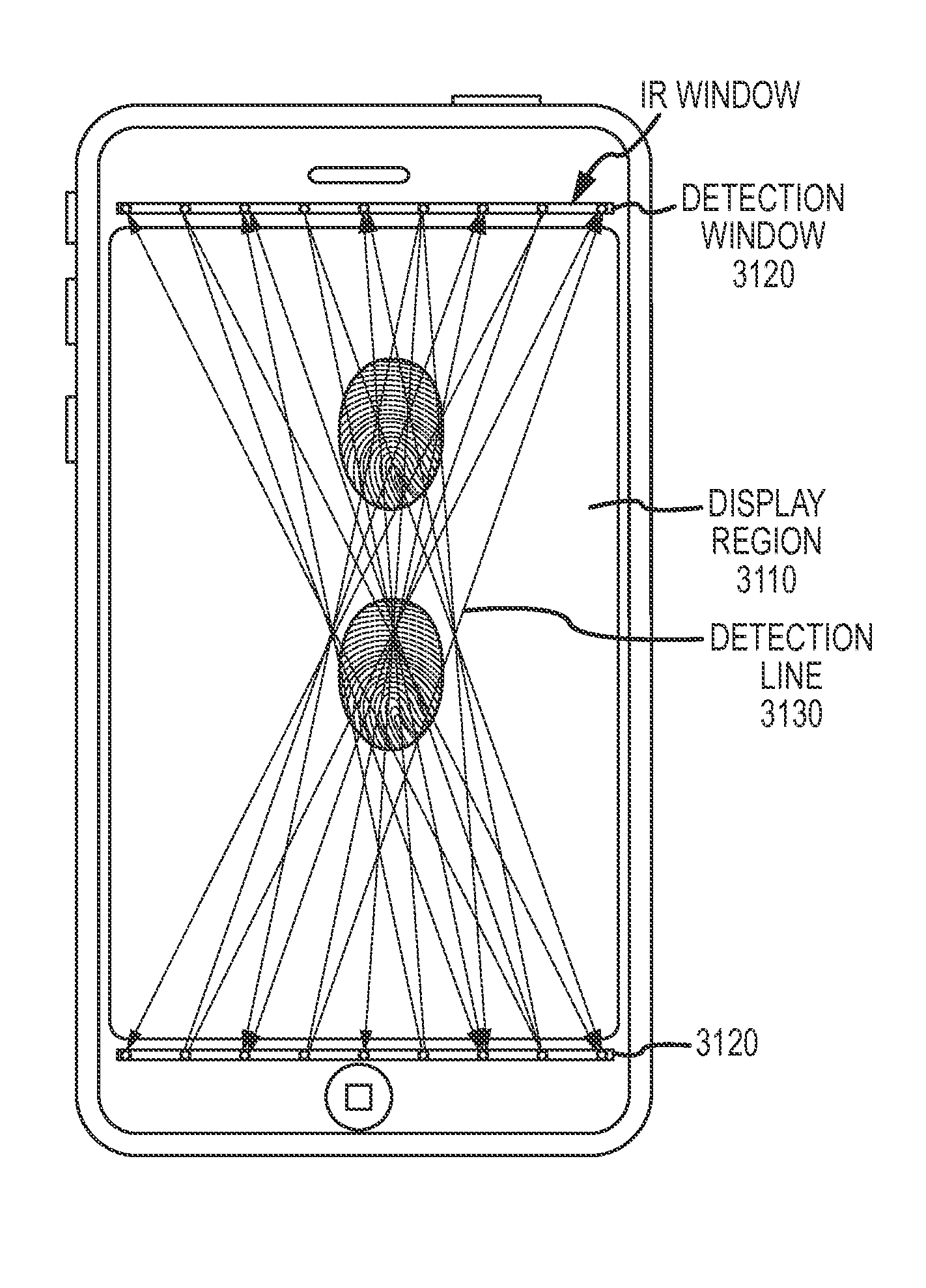
The patent text describes a technology that uses infrared sensing to determine the location on a touch device that a user's finger is touching. This helps the touch device to make an accurate determination of the amount of force applied by the user's finger. The infrared transmitters and receivers are positioned either below the edge of the cover glass or below a frame element that holds the cover glass, so they are not visible to the user. The technology also includes a method to position the infrared transmitters and receivers to the side of the cover glass or within an opaque substrate below the cover glass, so that the user's eye cannot see them. This technology helps improve the accuracy and sensory experience of touch interactions on touch devices.

Problems solved by technology

Each of these examples, as well as other possible considerations, can cause one or more difficulties for the touch device, at least in that inability to determine an amount of force applied by the user when contacting the touch device might cause a GUI or an application program to be unable to provide functions that would be advantageous.
When such functions are called for, inability to provide those functions may subject the touch device to lesser capabilities, to the possible detriment of the effectiveness and value of the touch device.

Method used


Image

  • Frustrated Total Internal Reflection and Capacitive Sensing
  • Frustrated Total Internal Reflection and Capacitive Sensing
  • Frustrated Total Internal Reflection and Capacitive Sensing

Examples


Embodiment Construction

Terminology

[0025]The following terminology is exemplary, and not intended to be limiting in any way.

[0026]The text “applied force”, and variants thereof, generally refers to a degree or measure of an amount of force being applied to a device. The degree or measure of applied force need not have any particular scale. For example, the measure of applied force can be linear, logarithmic, or otherwise nonlinear, and can be adjusted periodically (or otherwise, such as aperiodically, or otherwise from time to time) in response to one or more factors, either relating to applied force, location of touch, time, or otherwise.

[0027]The text “attenuated reflection”, and variants thereof, generally refers to a degree or measure of reflection less than 100% reflection, such as might occur at an interface where reflection of a transmitted signal is less than 100% reflection. For a first example, attenuated reflection can occur if the interface between two elements does not provide for 100% reflect...


PUM


Abstract

Detecting force and touch using FTIR and capacitive location. FTIR determines applied force by the user's finger within infrared transmit lines on a touch device. A pattern of such lines determine optical coupling with the touch device. Capacitive sensing can determine (A) where the finger actually touches, so the touch device more accurately infers applied force; (B) whether finger touches shadow each other; (C) as a baseline for applied force; or (D) whether attenuated reflection is due to a current optical coupling, or is due to an earlier optical coupling, such as a smudge on the cover glass. If there is attenuated reflection without actual touching, the touch device can reset a baseline for applied force for the area in which that smudge remains. Infrared transmitters and receivers are positioned where they are not visible to a user, such as below a frame or mask for the cover glass.

Description

BACKGROUND[0001]1. Field of the Disclosure[0002]This application generally relates to force sensing using frustrated total internal reflection (FITR) and capacitive techniques, and other matters.[0003]2. Background of the Disclosure[0004]Touch devices generally provide for identification of positions where the user touches the device, including movement, gestures, and other effects of position detection. For a first example, touch devices can provide information to a computing system regarding user interaction with a graphical user interface (GUI), such as pointing to elements, reorienting or repositioning those elements, editing or typing, and other GUI features. For a second example, touch devices can provide information to a computing system suitable for a user to interact with an application program, such as relating to input or manipulation of animation, photographs, pictures, slide presentations, sound, text, other audiovisual elements, and otherwise.[0005]It sometimes occurs ...

Claims


Application Information

Patent Timeline
IPC IPC(8): G06F3/044G06F3/041
CPCG06F3/0421G06F2203/04105G06F2203/04106G06F2203/04109G06F3/044G06F3/04162
Inventor GRUNTHANER, MARTIN P.RICHARDS, PETER W.TEIL, ROMAIN A.HOTELLING, STEVEN P.
Owner APPLE INC
Learn More