Dust Free Drill System

a technology of dust-free drills and drill bits, which is applied in the direction of manufacturing tools, metal-working machine components, portable power-driven tools, etc., can solve the problems of laborious cleanup, a large amount of dust and chips, and a cloud of debris in the surrounding work area

Inactive Publication Date: 2014-04-03
SULLIVAN MARK D
View PDF29 Cites 20 Cited by
  • Summary
  • Abstract
  • Description
  • Claims
  • Application Information

AI Technical Summary

Benefits of technology

[0031]In another aspect, wherein the first and second device are held together by the first and second portions of the latch on the first and second half cylinders respectively.

Problems solved by technology

These type of drills when used on concrete structures or similar surfaces generate a great deal of dust and chips filling the surrounding work area with a cloud of debris.
This byproduct of a simple construction procedure can severely impact the workspace environment leading to a laborious cleanup.

Method used


Image

  • Dust Free Drill System
  • Dust Free Drill System
  • Dust Free Drill System

Examples


Embodiment Construction

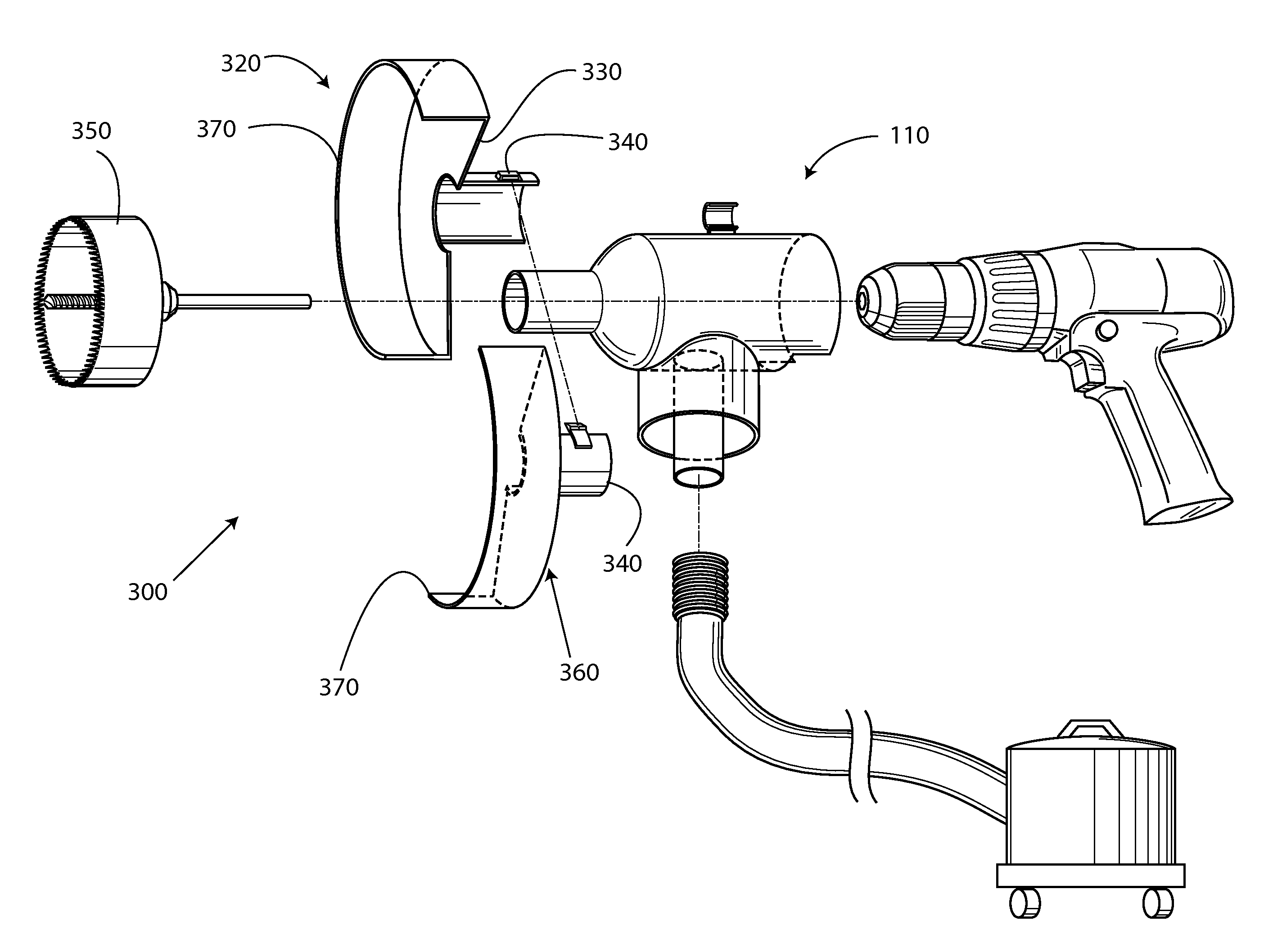
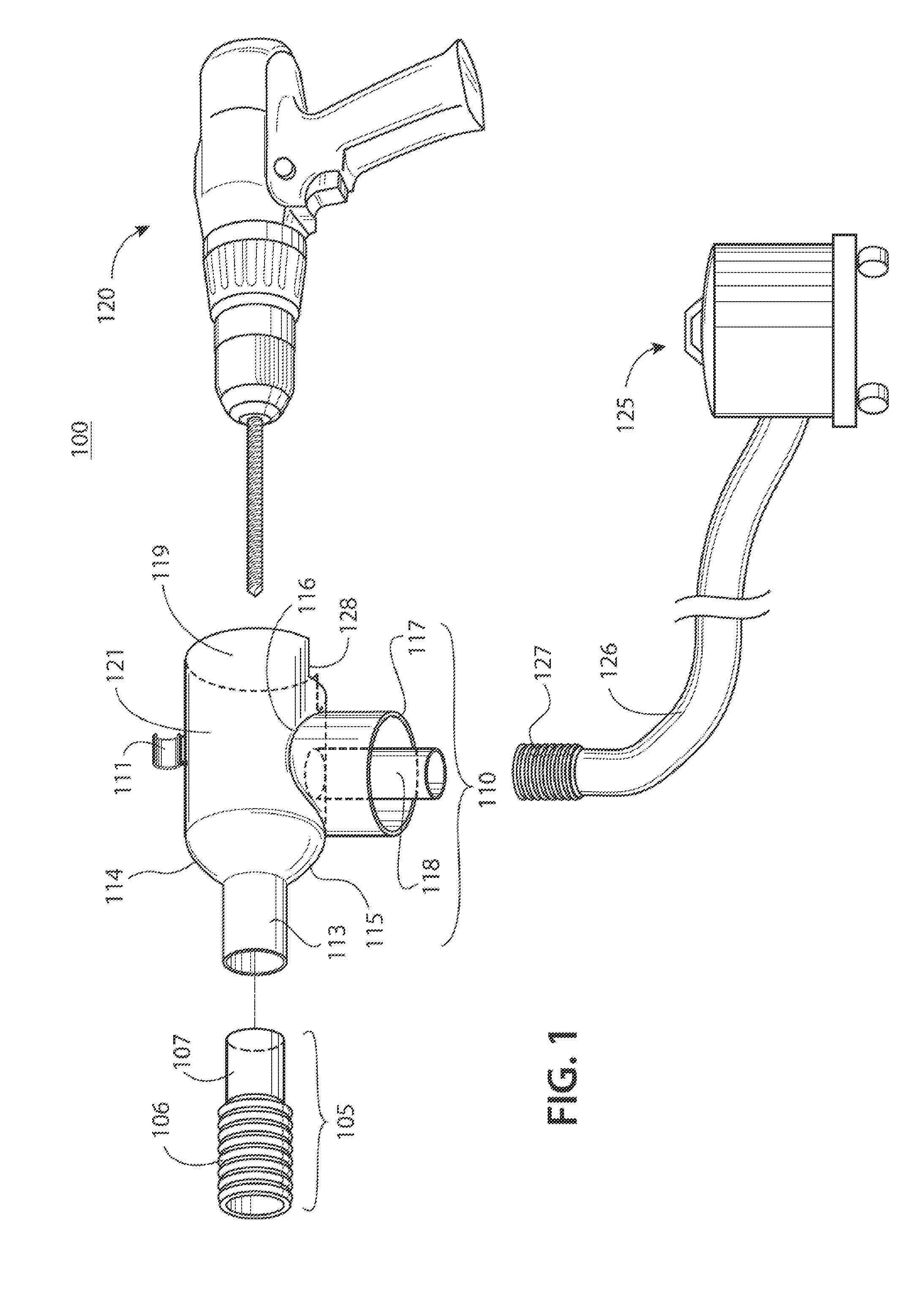
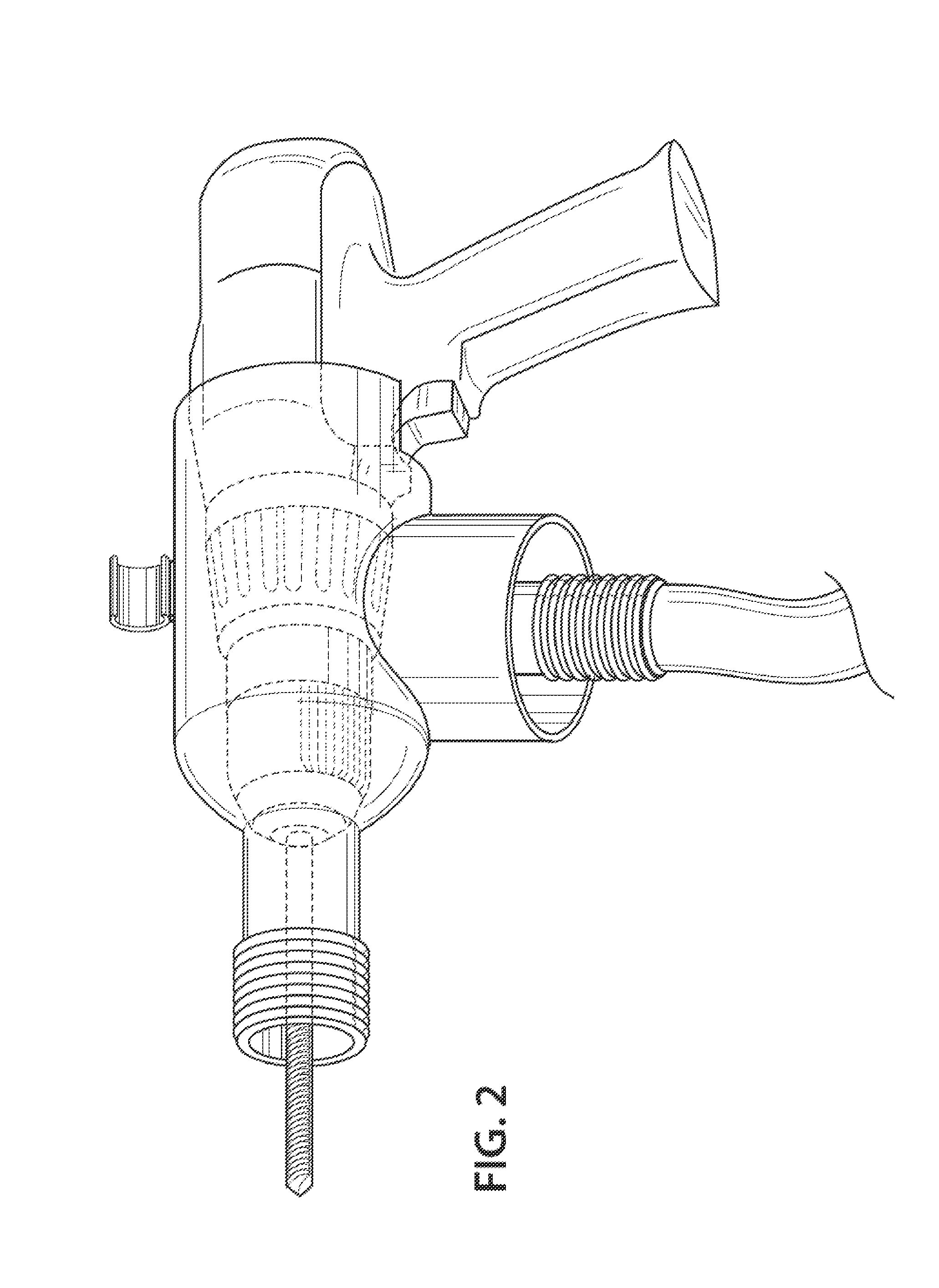
[0038]The following detailed description is merely exemplary in nature and is not intended to limit the described embodiments or the application and uses of the described embodiments. As used herein, the word “exemplary” or “illustrative” means “serving as an example, instance, or illustration.” All of the implementations described below are exemplary implementations provided to enable persons skilled in the art to make or use the embodiments of the disclosure and are not intended to limit the scope of the disclosure, which is defined by the claims. For purposes of description herein, the terms “upper”, “lower”, “left”, “rear”, “right”, “front”, “vertical”, “horizontal”, and derivatives thereof shall relate to the invention as oriented in each figure. Furthermore, there is no intention to be bound by any expressed or implied theory presented in the preceding technical field, background, brief summary or the following detailed description. It is also to be understood that the specifi...


PUM

PropertyMeasurementUnit
shapeaaaaaaaaaa
brittleaaaaaaaaaa
poweraaaaaaaaaa

Abstract

Hammer drills and similar devices have an ongoing dust and debris problem that is solved by a protector device covering the drill in a main body protector shielding a user from the materials. The protector device has an evacuation region on its underside with multi dimensional adapters for attaching hoses of varying sizes. Additionally, an insertable collapsible accordion cylinder assists in covering the debris falling from different size drills being used. A second embodiment has a circular saw dust protector attachment arranged as two half moons or 1/4 moon and 3/4 moon having a central cylinder at their respective tops that are to be held together with a mechanical latch.

Description

CROSS REFERENCE TO RELATED APPLICATIONS[0001]This application claims benefit of previously filed provisional patent application 61 / 707,431 filed on Sep. 28, 2012.FIELD OF THE INVENTION[0002]This invention relates to devices to shield a construction device. More particularly, the invention relates to an attachment device that concentrates debris, chips and dust produced from a drilling device and deposits it into a secure collection machine in order to avoid polluting the surrounding environment.BACKGROUND OF THE INVENTION[0003]A hammer drill is known by various other names such as a rotary hammer, roto-drill or hammering drill. This type of drill has a rotary action interacting with a hammering action. The hammering action provides a hammer strike that quickly pulverizes a brittle surface and permits faster drilling with less effort. These drills are typically electric or battery powered, whilst larger units use electro-pneumatic technology to provide sufficient power.[0004]Another ...

Claims


Application Information

Patent Timeline
Patent Type & Authority Applications(United States)
IPC IPC(8): B23Q11/00
CPCB23Q11/0046B25F3/00Y10T408/50Y10T409/304088B23B2270/62Y02P70/10
Inventor SULLIVAN, MARK
Owner SULLIVAN MARK D
Why Eureka
Try Eureka