Server for home appliance network system

a home appliance and network system technology, applied in the field of server for home appliance network system, to achieve the effect of reducing complexity and time in screen switching

Active Publication Date: 2014-04-03
PANASONIC INTELLECTUAL PROPERTY MANAGEMENT CO LTD
View PDF10 Cites 1 Cited by
  • Summary
  • Abstract
  • Description
  • Claims
  • Application Information

AI Technical Summary

Benefits of technology

[0011]The server of the invention can reduce complexity and time in screen switching just after logging-in by displaying a preset variable initial screen on a portable terminal in response to a position of the portable terminal.

Problems solved by technology

There is however a problem that a user needs to operate the terminal in order to display an objective page after logging-in, because a top page is initially displayed on a screen of the terminal after logging-in in many conventional service systems such as the system as shown in Document 1.

Method used


Image

  • Server for home appliance network system
  • Server for home appliance network system
  • Server for home appliance network system

Examples


Embodiment Construction

[0024]Hereafter embodiments of the present invention will be described with reference to figures. In each figure, like kind elements will be assigned the same reference numerals and the explanation will be omitted. The embodiments only show examples of the invention, and the invention is not limited to the embodiments.

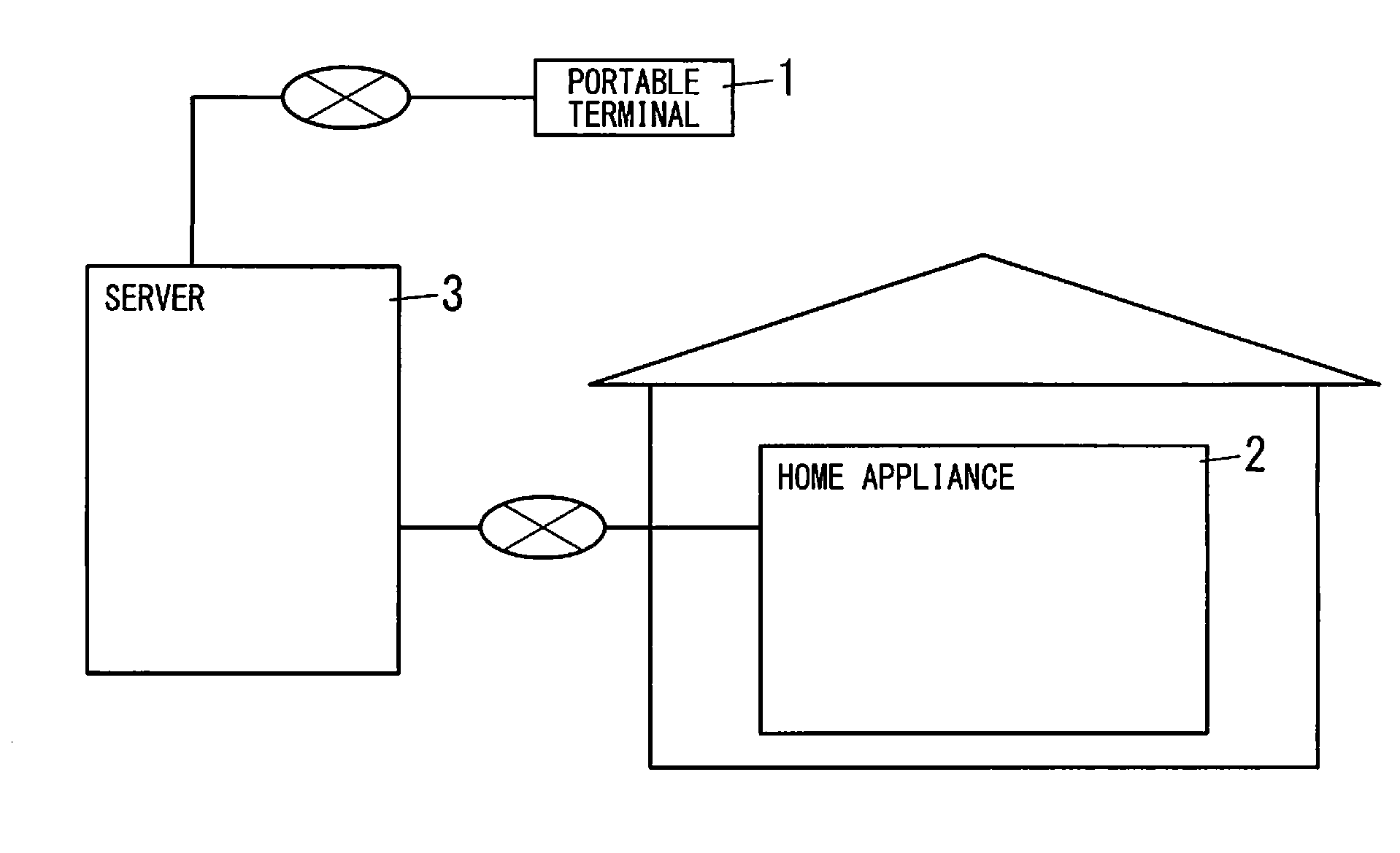
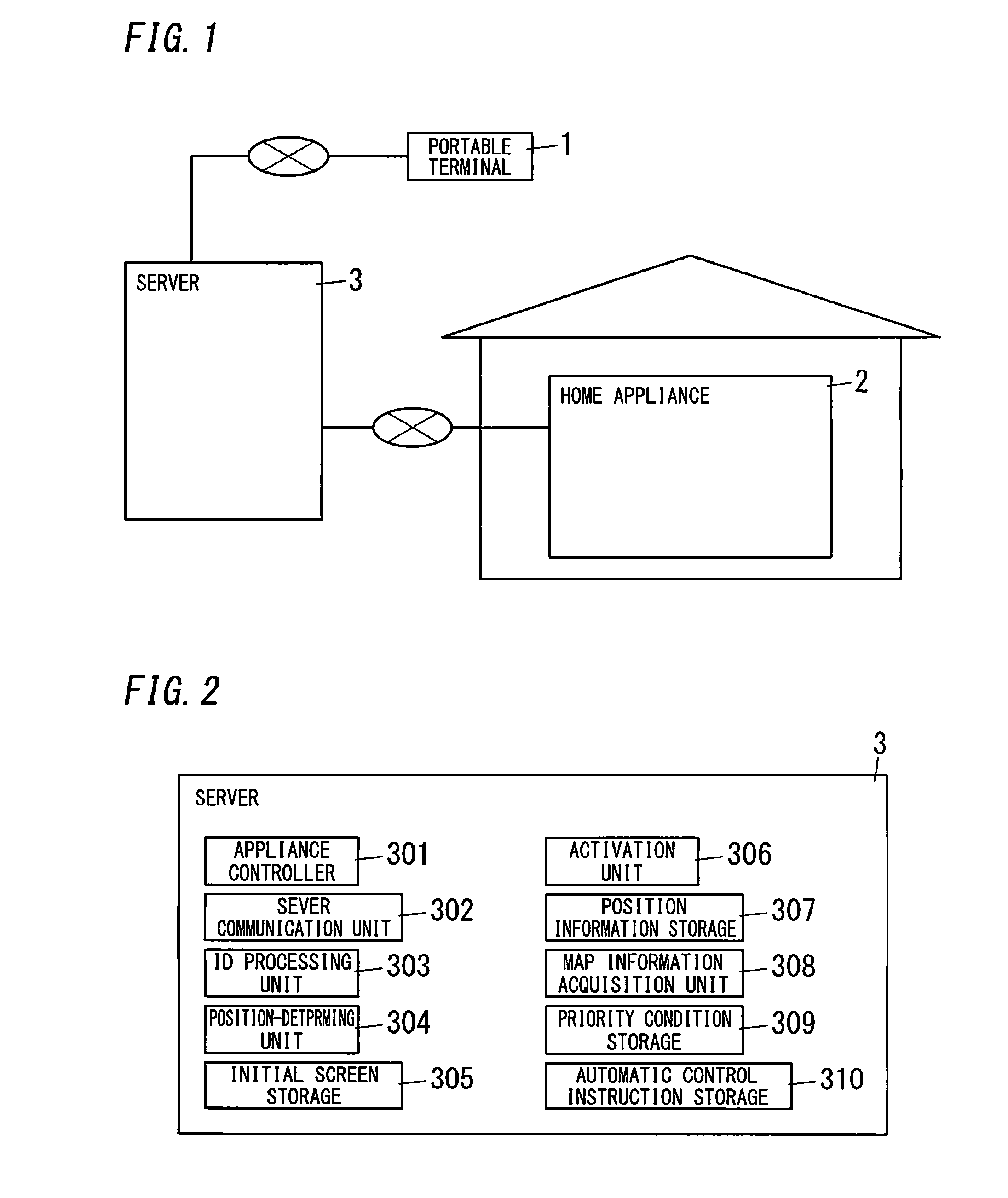
[0025]FIGS. 1 and 2 show an embodiment of the invention. A server 3 for a home appliance network system (hereinafter simply referred to as a “server 3”) constitutes the home appliance network system along with at least a portable terminal 1 and at least a home appliance 2. The portable terminal 1 is, for example, a mobile phone or the like. The home appliance 2 is, for example, an appliance used in a house, such as a lighting apparatus, an air-conditioner, an electronic lock, a security camera or the like. These home appliances 2 are configured to communicate with the portable terminal 1 and the server 3 via the internet through a home gateway device. The portable term...


PUM


Abstract

A server (3) includes a server communication unit (302) for communicating with a portable terminal (1) and a home appliance (2), a position-determining unit (304) for acquiring information on a position of the terminal (1) during communication, an initial screen storage (305) for storing different position conditions and a collection of screen information defining respective content of initial screens corresponding to the conditions, and an activation unit (306). If position information obtained based on the information on the position acquired through the position-determining unit (304) corresponds to any position condition of the different position conditions, the unit (306) retrieves screen information defining content of an initial screen corresponding to the position condition from the storage (305) to provide the terminal (1) with the information.

Description

TECHNICAL FIELD[0001]The invention relates to a server for a home appliance network system.BACKGROUND ART[0002]Conventionally, there is proposed a server for a home appliance network system such as, for example, a remote control monitoring service system for housing life equipment unit through a portable terminal to be operated by a contracted user described in Japanese Patent Application Publication Number 2002-109203 (hereinafter referred to as “Document 1”). The remote control monitoring service system is configured to perform automatic control of household appliances installed in a user's house based on position information of a user's portable terminal.[0003]There is however a problem that a user needs to operate the terminal in order to display an objective page after logging-in, because a top page is initially displayed on a screen of the terminal after logging-in in many conventional service systems such as the system as shown in Document 1. In some conventional service syst...

Claims


Application Information

Patent Timeline
Patent Type & Authority Applications(United States)
IPC IPC(8): H04W4/02H04L29/08
CPCH04L67/04H04W4/025
Inventor MATSUMOTO, KOJI
Owner PANASONIC INTELLECTUAL PROPERTY MANAGEMENT CO LTD
Why Eureka
Try Eureka