Liquid ejecting apparatus

Inactive Publication Date: 2014-04-10
SEIKO EPSON CORP
View PDF10 Cites 8 Cited by
  • Summary
  • Abstract
  • Description
  • Claims
  • Application Information

AI Technical Summary

Benefits of technology

The invention allows for easier installation of a liquid ejecting apparatus by making it simpler to install the liquid supply tube.

Problems solved by technology

As a result, there is a problem that requires complicated work when leading around the ink supply tube while restricting the movement of the ink supply tube in a direction crossing the length direction thereof.

Method used


Image

  • Liquid ejecting apparatus
  • Liquid ejecting apparatus
  • Liquid ejecting apparatus

Examples


first embodiment

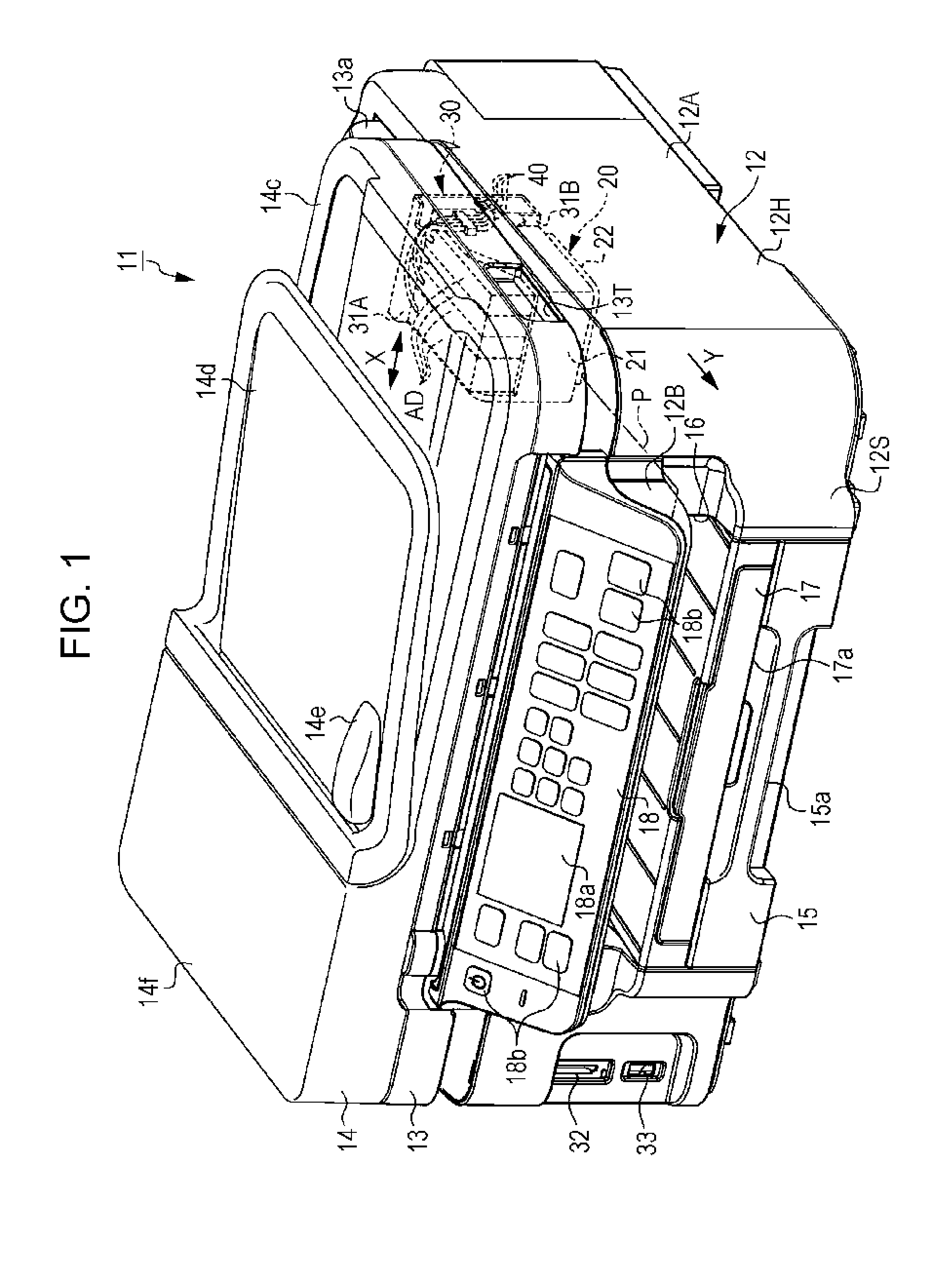
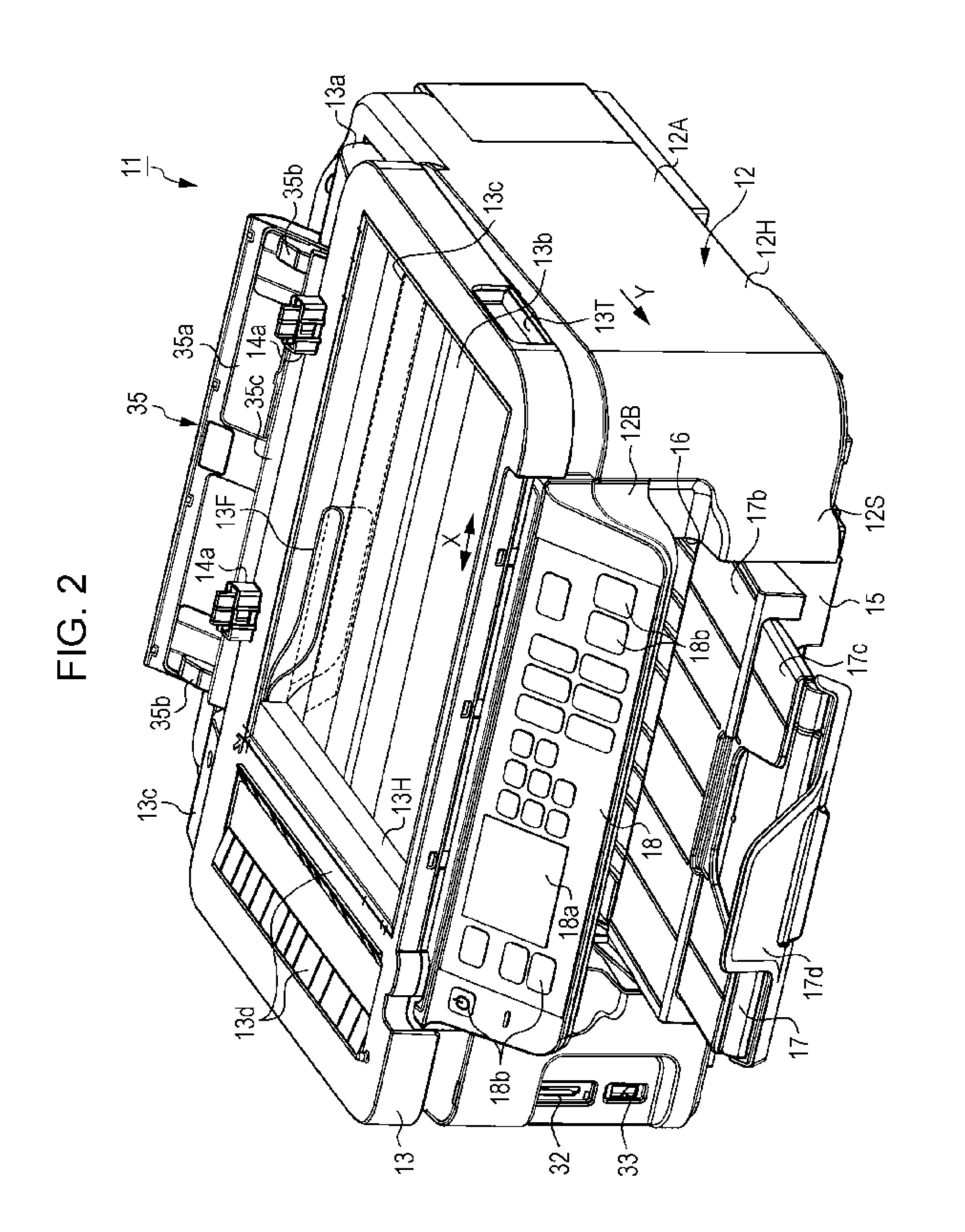
[0070]As shown in FIG. 1, a printer 11 of this embodiment is a so-called multifunction machine which includes a print function section 12A (a printer unit) that includes an apparatus main body 12 having a print function, and an image reading section 13 (a scanner unit) having a scan function which is provided above the apparatus main body 12. In the following description, the printer that is a multifunction machine shall be referred to as a first printer 11.

[0071]The first printer 11 receives the supply of ink from an ink tank 19T (refer to FIG. 3) as an example of a liquid accommodation section having a substantially rectangular parallelepiped shape, which is a separate body, through an ink supply tube 40 (refer to FIG. 3) which is disposed by a fixing section.

[0072]In the first printer 11, on the lower portion side in the gravity direction thereof, the print function section 12A as an example of a casing section having a printing section 20 built-in is disposed, and on the other h...

second embodiment

[0129]Next, a second embodiment relating to the disposition of the ink supply tube 40 will be described with reference to FIGS. 4B and 6. In the second embodiment, the gap forming member between the print function section 12A and the image reading section 13 is the spacer 51 which is fixed to the upper surface portion 12U. The spacer 51 is a tubular body 51B having a substantially cylindrical shape when viewed from the axial direction. In addition, in the description of this embodiment, the same constituent members as those in the first embodiment described above are denoted by the same reference numerals as those in the first embodiment and the description thereof is omitted.

[0130]As shown in FIG. 6, the tank unit 19 which accommodates a plurality of ink tanks 19T is located on the home position side with respect to the casing 12H. The ink supply tube 40 with one end portion connected to each ink tank 19T is fixed to the upper surface portion 12U on the opposite side to the support...

third embodiment

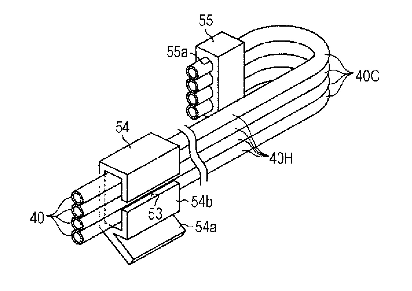
[0142]Next, a third embodiment relating to the disposition of the ink supply tube 40 will be described with reference to FIGS. 7, 8A, and 8B. In the third embodiment, the gap forming member between the print function section 12A and the image reading section 13 is an inclined block 54 that can obliquely retain the plurality of ink supply tubes 40. In addition, in the description of this embodiment, the same constituent members as those in the first embodiment described above are denoted by the same reference numerals as those in the first embodiment and the description thereof is omitted.

[0143]As shown in FIG. 7, the inclined block 54 that is an example of the spacer is fixed to a portion of a peripheral portion on the front side of the opening portion 12K in the upper surface portion 12U of the casing 12H. The inclined block 54 retains the plurality of ink supply tubes 40 with respect to an opening plane of the opening portion 12K in a state where a plane (the tube plane) passing t...


PUM


Abstract

A liquid ejecting apparatus includes a main body in which an opening portion exposing at least a portion of a carriage moving area, a cover section displaceable with the main body, an ink tank that is located outside the main body, an ink supply tube for supplying ink from the ink tank to a head, and a spacer that forms a gap between the main body and the cover. An accommodation section is configured by a casing portion formed to protrude in a discharge direction of paper. An operation panel section is configured by a casing portion exhibiting an inclined surface. The spacer forms a gap having a size that does not shut off at least an ink flow path of the ink supply tube and passes the ink supply tube through the formed gap.

Description

BACKGROUND[0001]1. Technical Field[0002]The present invention relates to a liquid ejecting apparatus that ejects liquid onto a target.[0003]2. Related Art[0004]In the past, as one type of a liquid ejecting apparatus, an ink jet type printer has been known which performs printing (recording) by ejecting ink from a liquid ejecting head onto a target such as paper. Then, in such a printer, in order to continuously and stably supply ink to the liquid ejecting head in a case of performing a relatively large amount of printing, a configuration to supply ink from an ink tank having relatively large ink accommodation capacity through an ink supply tube to an ink cartridge has been proposed (refer to Taiwan Patent No. 538909, for example).[0005]In the printer having such a configuration, the liquid ejecting head is mounted on a carriage provided so as to be able to reciprocate in a main scanning direction with respect to paper in a casing section (a main body housing) of a main body. Then, t...

Claims


Application Information

Patent Timeline
IPC IPC(8): B41J2/175
CPCB41J2/175B41J2/17509B41J29/02
Inventor SUZUKI, YUTOSHIMIZU, SATOSHISHIMOMURA, MASAKISUZUKI, NOBUTAKATEZUKA, SEIJI
Owner SEIKO EPSON CORP
Why Eureka
Try Eureka