High Voltage DC/DC Converter With Cascaded Resonant Tanks

a resonant tank and high-voltage technology, applied in the field of converters, can solve the problems of increasing reducing the overall size and weight of the power converter and power station, and difficult interconnection of the dc transmission and distribution network to form a dc power grid

Active Publication Date: 2014-04-10
ALSTOM TECH LTD
View PDF4 Cites 17 Cited by
  • Summary
  • Abstract
  • Description
  • Claims
  • Application Information

AI Technical Summary

Problems solved by technology

However, interconnecting the DC transmission and distribution networks to form a DC power grid is difficult because different DC networks may operate at different voltage levels depending on various factors as outlined above.
Transformers used in high voltage applications however tend to be bulky and heavy.
This not only adds to the overall size and weight of the power converter and power station, but also leads to increased costs associated with transport of the transformers to the site of the power station.
In general, the structure of each o...

Method used


Image

  • High Voltage DC/DC Converter With Cascaded Resonant Tanks
  • High Voltage DC/DC Converter With Cascaded Resonant Tanks
  • High Voltage DC/DC Converter With Cascaded Resonant Tanks

Examples


first embodiment

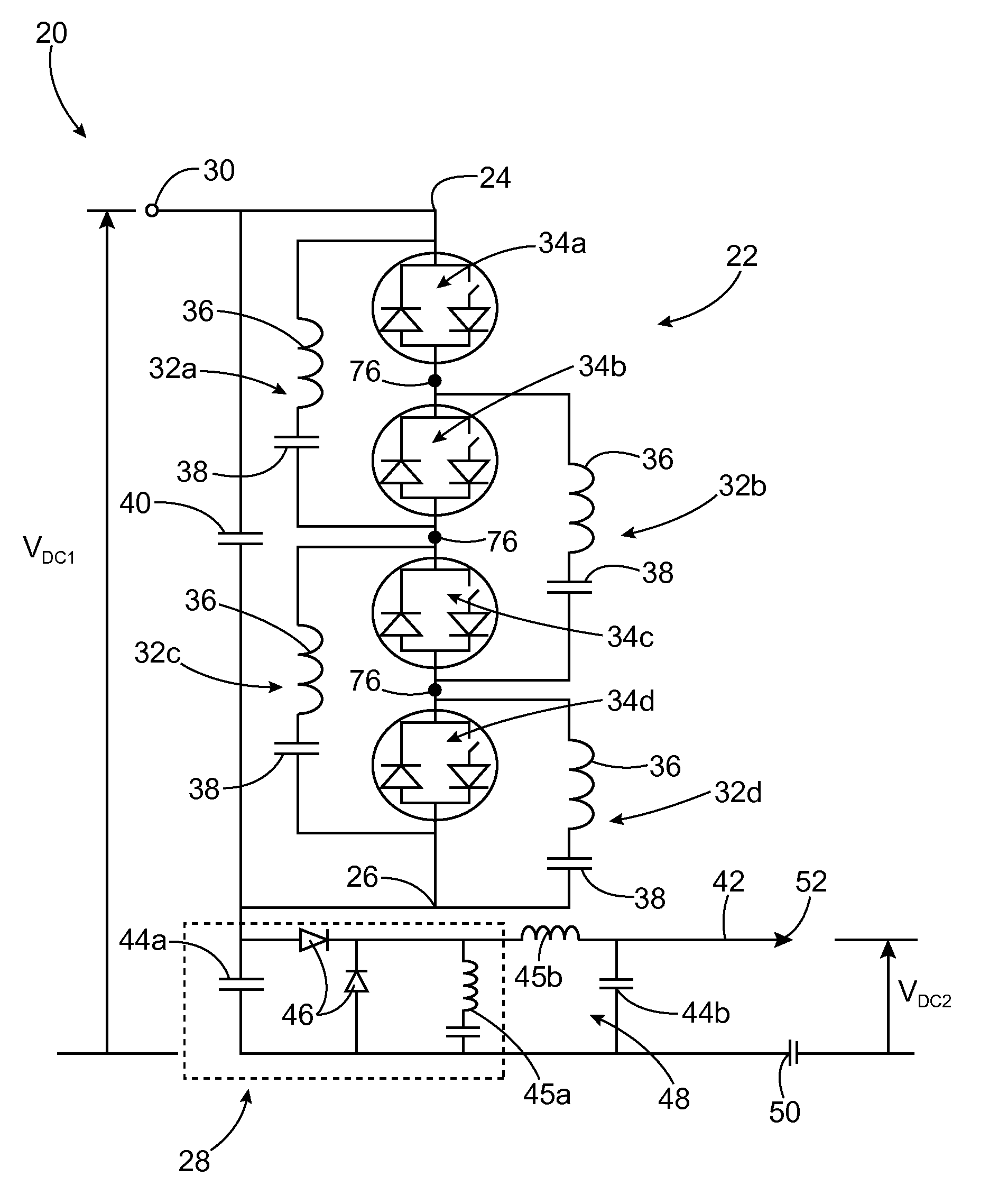
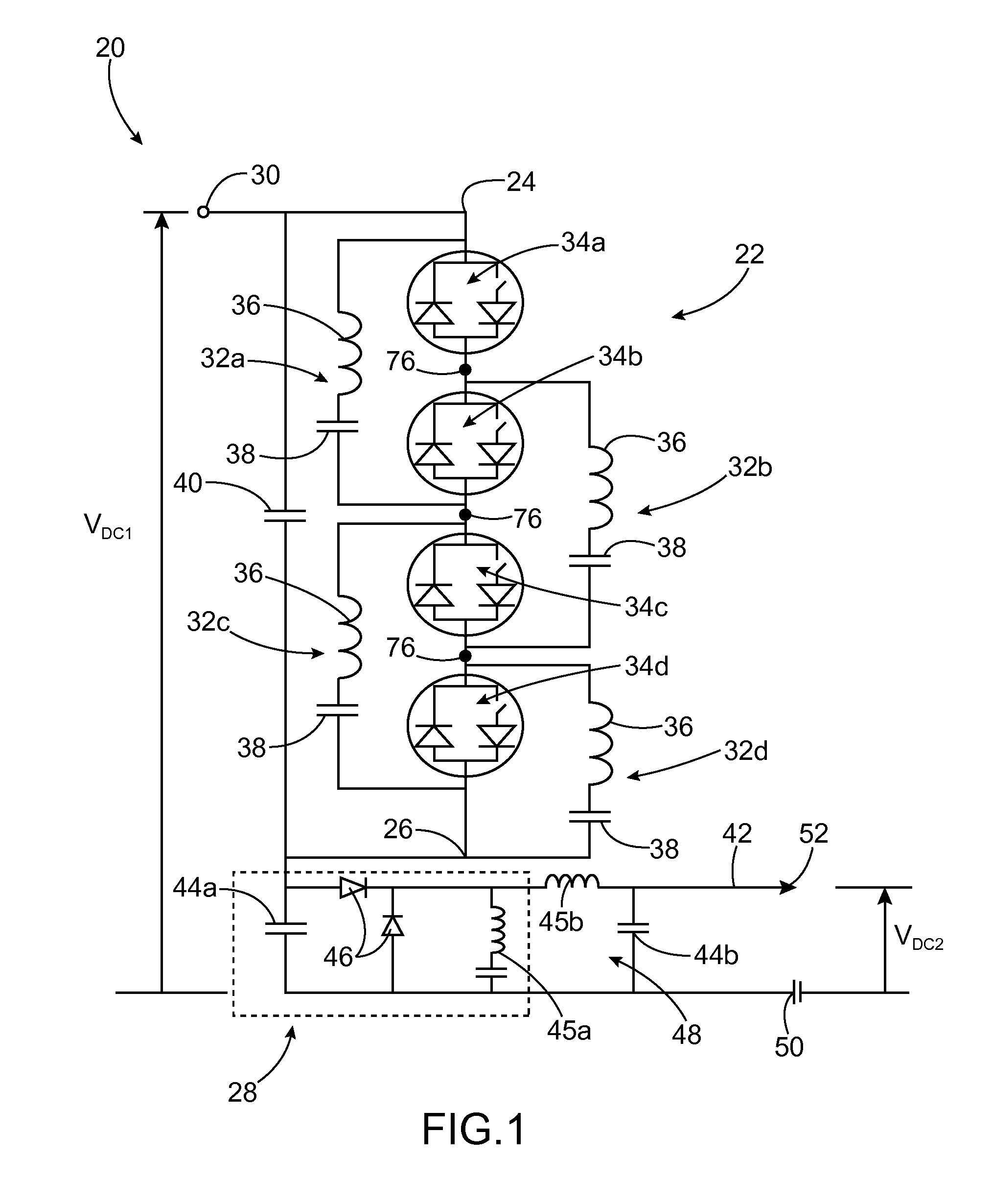
[0063]A converter 20 according to the invention is shown in FIG. 1. The converter 20 could be considered a Resonant Charge Transfer Converter because of the manner in which functions, as set out below. For the sake of conciseness, however, it will be referred to as a converter throughout this specification.

[0064]The converter 20 comprises a primary charge transfer converter 22 having a first primary terminal 24 and a second primary terminal 26. The converter 20 also includes an auxiliary unit 28 which is connected to the second primary terminal 26 of the primary charge transfer converter 22.

[0065]The first primary terminal may be connected in use to a first DC network 30 which carries a first DC voltage, VDC1. The first primary terminal 24 may be connected to the first DC network 30 via one or more inductors (not shown).

[0066]The primary charge transfer converter 22 includes first, second, third and fourth charge transfer elements 32a,32b,32c,32d which are connected with first, seco...

second embodiment

[0123]A converter 80 according to the invention is shown in FIG. 5.

[0124]The second converter 80 shown in FIG. 5 is similar to the first converter 20 shown in FIG. 1 and like features have the same reference numerals. However, two ways in which the second converter 80 differs from the first converter 20 is that each primary switching element 34a, 34b, 34c, 34d is a single diode switch and the auxiliary unit 28 defines a charge generator in the form of an oscillator circuit 70.

[0125]In alternative arrangements of the second converter 80 (not shown) the single diode switch can be replaced by another switch arrangement such as, for example, an IGBT arranged in parallel with a diode but with the IGBT switched off.

[0126]The oscillator circuit 70 includes an auxiliary switch 72 and a passive circuit 74 tuned to the resonant frequency of the resonant circuits. The oscillator circuit 70 further includes a filter 48 connected to the auxiliary terminal 42 and a connection to ground 50.

[0127]I...

third embodiment

[0159]FIG. 8 shows a first converter assembly 100 according to the invention.

[0160]The first converter assembly includes a converter 20;80 in which the first primary terminal 24 is connected to a positive terminal of a first DC network 30 while the auxiliary terminal 42 is connected to a negative terminal of the first DC network 30.

[0161]A plurality of secondary terminals 76 are connected to positive, negative and ground terminals of a second DC network 52.

[0162]Such a converter assembly 100 permits power conversion between different bipole DC networks 30,52.


PUM


Abstract

A converter, for use in high voltage direct and alternating current power transmission comprises a primary charge transfer converter. The charge transfer converter includes first and second primary terminals for connection to one or more electrical networks. The primary charge transfer converter also includes a plurality of charge transfer elements and a plurality of primary switching elements which are connected in a cascade circuit between the first and second primary terminals. Each charge transfer element includes at least one resonant circuit. The primary switching elements are operable to selectively cause charging and discharging of each resonant circuit to transfer charge between the charge transfer elements and thereby create a voltage difference between the first and second primary terminals.

Description

TECHNICAL FIELD[0001]This invention relates to a converter for use in high voltage direct current (DC) and alternating current power transmission.BACKGROUND[0002]Power transmission networks typically include interconnected electrical networks operating at different voltages. The variation in these operating voltages arises as a result of many factors including the size and locality of the individual electrical network, the local power requirements and so on.[0003]In high voltage direct current (HVDC) power transmission networks, alternating current power is generated by the generator plant at a low voltage level in the range of a few kV before being stepped up in a collector station to a higher voltage level in the range of a few hundred kV and then converted to direct current power for transmission via overhead lines and / or undersea cables. This conversion removes the need to compensate for the AC capacitive load effects imposed by the transmission line or cable, and thereby reduce...

Claims


Application Information

Patent Timeline
IPC IPC(8): H02M3/335
CPCH02M3/33507H02J3/36H02M3/07H02M7/103Y02E60/60H02M3/3376Y02B70/10H02M3/338
Inventor WHITEHOUSE, ROBERT S.
Owner ALSTOM TECH LTD
Why Eureka
Try Eureka