Chain tensioner

a chain tensioner and tensioner technology, applied in the direction of belts/chains/gearrings, mechanical instruments, belts/chains/gears, etc., can solve the problems of difficult universal use of the tensioner, the inability to apply the configuration to a design in which oil is supplied laterally, etc., and achieves less space, shorter and smaller

Active Publication Date: 2014-04-10
TSUBAKIMOTO CHAIN CO
View PDF7 Cites 20 Cited by
  • Summary
  • Abstract
  • Description
  • Claims
  • Application Information

AI Technical Summary

Benefits of technology

[0038]With the structure as set forth in claim 8, one end of the coil spring seated on the bottom of the plunger bore is restricted from moving sideways by the tapered surface, so that looseness or displacement of the coil spring in the late...

Problems solved by technology

However, this configuration cannot be applied to a design in which oil is supplied laterally.
Universal use of the tensioner was diffic...

Method used


Image

  • Chain tensioner
  • Chain tensioner
  • Chain tensioner

Examples


embodiment 1

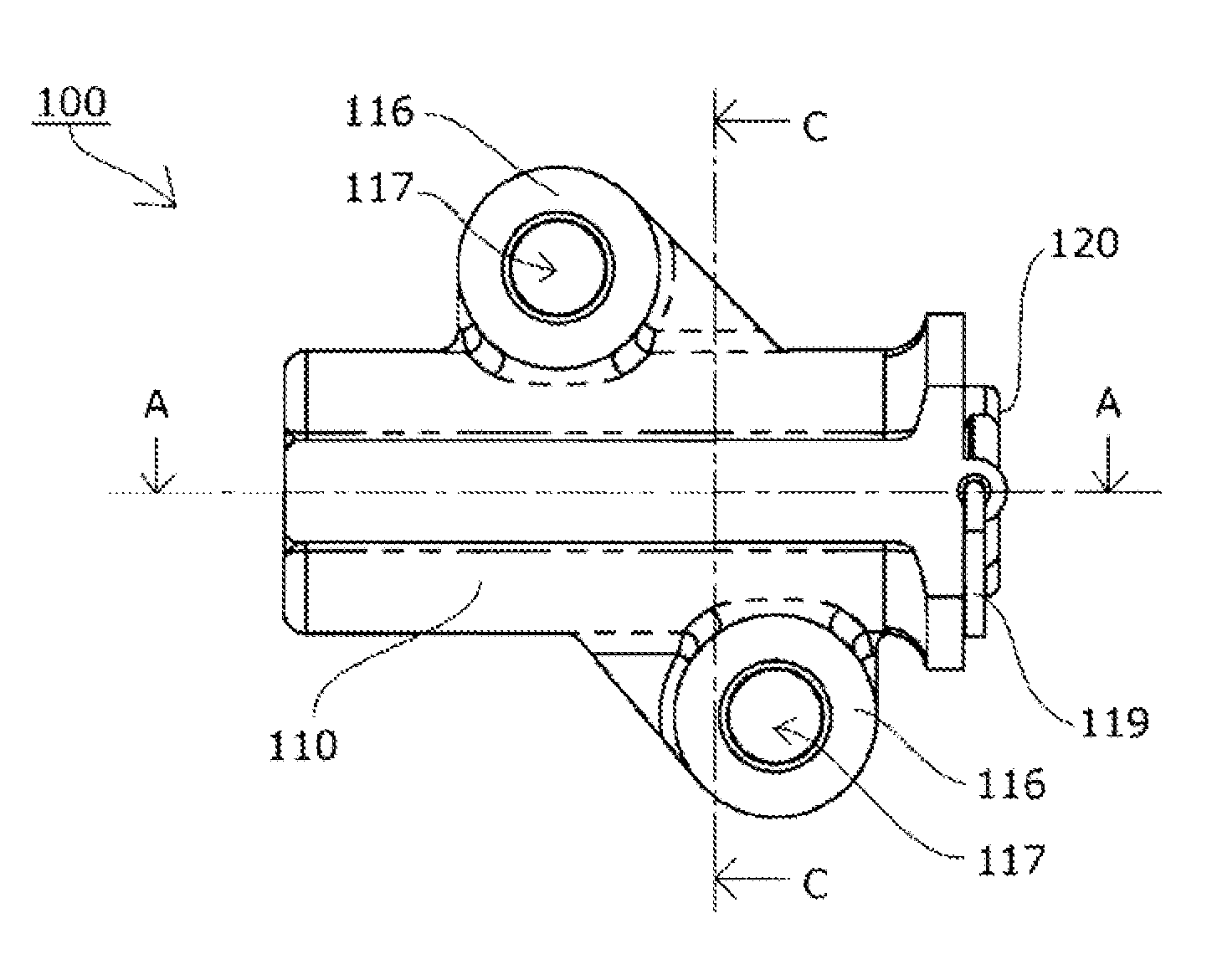
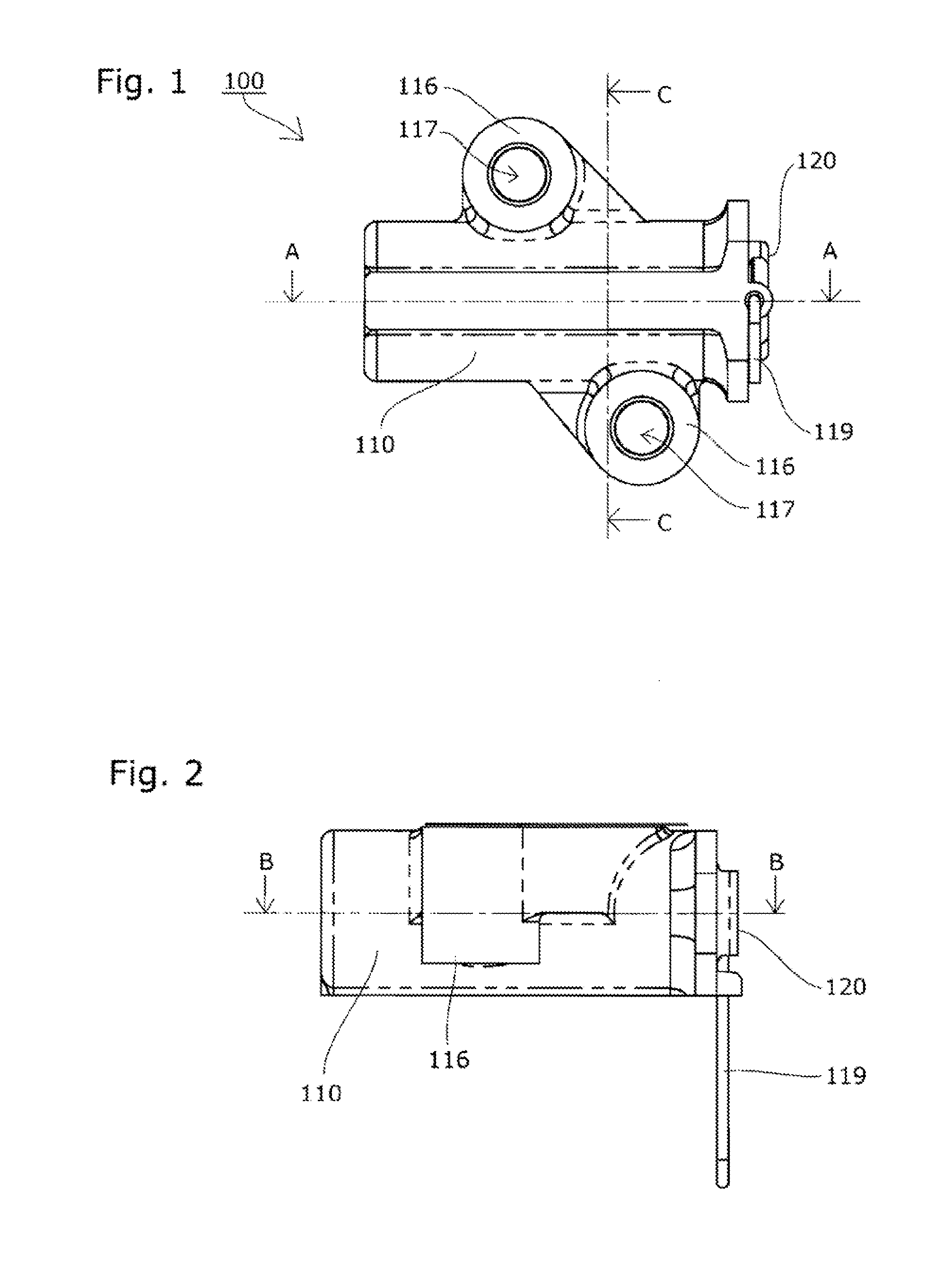
[0054]A chain tensioner 100 according to a first embodiment of the present invention will be described with reference to the drawings.

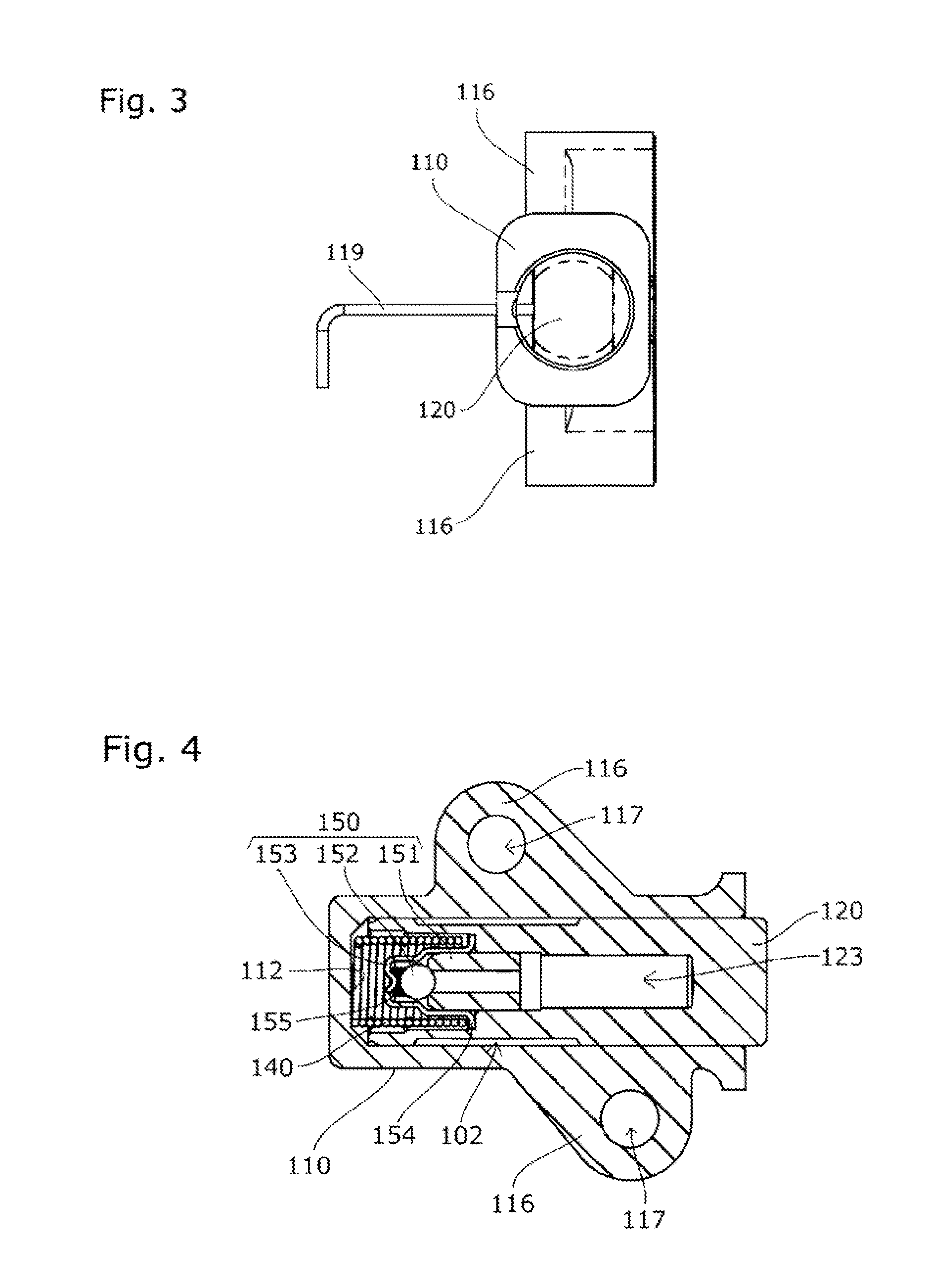
[0055]The chain tensioner 100 according to a first embodiment of the present invention includes, as shown in FIG. 1 to FIG. 9, a tensioner body 110 having a cylindrical plunger bore 111 with an open end, a cylindrical plunger 120 slidable within the plunger bore 111, and a coil spring 140 that is urging unit accommodated inside an oil pressure chamber 101 formed between the plunger bore 111 and the rear end of the plunger 120 such as to be able to expand and contract and to urge the plunger 120 outward.

[0056]The chain tensioner 100 according to this embodiment is securely mounted inside an engine having a chain guide mechanism. For this purpose, the tensioner body 110 has mounting parts 116 with mounting holes 117 for bolts or the like to pass through as shown in FIG. 1 to FIG. 5.

[0057]An oil supply hole 114 is formed in the cylindrical surface 113 of...

embodiment 2

[0085]The chain tensioner according to a second embodiment of the present invention has a different type of check valve, and various constituent parts have different shapes, sizes, and positional relationships with each other, as compared to the chain tensioner 100 according to the previously described first embodiment, as shown in FIG. 10 (reference numerals in the drawing are the same as those of the first embodiment).

[0086]The ball seat 151 of the check valve 150 in this embodiment also serves as a ball guide. The retainer 153 is disc-shaped.

[0087]The plunger hole 124 is inclined from the outermost end of the supply chamber 102 to open into the oil reservoir chamber 123.

[0088]With this embodiment, the oil flowing through the leak groove 125 into the supply chamber 102 can be recovered into the oil reservoir chamber 123 even more smoothly because of the shape of the plunger hole 124 opened diagonally outward.

embodiment 3

[0089]The chain tensioner according to a third embodiment of the present invention has the plunger hole 124 located at a different position as compared to the chain tensioner 100 according to the previously described first embodiment, as shown in FIG. 11 (reference numerals in the drawing are the same as those of the first embodiment).

[0090]The plunger hole 124 in this embodiment is oriented at right angles from the oil supply hole 114 formed in the cylindrical surface 113 of the plunger bore 111 so that it opens upward when the chain tensioner 100 is mounted in the engine.

[0091]The leak groove 125 in the outer circumference of the plunger 120 on the side of the oil pressure chamber 101 is located at the same phase position as that of the plunger hole 124.

[0092]With this embodiment, even a slightest leak of oil caused by a reverse flow from the oil reservoir chamber 123 into the oil supply hole 114 can be prevented reliably after the stop of oil supply (in the case with an engine, a...


PUM


Abstract

To provide a chain tensioner that has a simple structure, is universally usable and capable of supplying sufficient and necessary oil when restarted after a long time after the stop of oil supply, and enables reduction of its length and size. Urging unit 140 provided in an oil pressure chamber 101 to be extendable and contractible urges a plunger 120 outward from a plunger bore 111 in a tensioner body 110 of the chain tensioner 100. A connection groove 122 is formed in the outer circumference of the plunger 120 to form a supply chamber 102. An oil reservoir chamber 123 is formed inside the plunger 120. A leak groove 125 is formed in the outer circumference of the plunger 120 on the side of the oil pressure chamber 101 such as to extend into the supply chamber 102.

Description

BACKGROUND OF THE INVENTION[0001]1. Field of the Invention[0002]The present invention relates to a chain tensioner that includes a tensioner body having a cylindrical plunger bore with an open end, a cylindrical plunger slidable within the plunger bore, and urging unit accommodated inside an oil pressure chamber formed between the plunger bore and the rear end of the plunger such as to be able to expand and contract and to urge the plunger outward, the chain tensioner being capable of maintaining suitable tension of a chain.[0003]2. Description of the Related Art[0004]Chain tensioners are commonly used for maintaining suitable tension of chains. In a chain guide mechanism that slidably guides a transmission chain such as an endless roller chain passing over respective sprockets of a crankshaft and a cam shaft inside an engine room with a guide shoe, for example, it is known to urge a pivoting chain guide having the guide shoe with a chain tensioner to maintain suitable tension.[0005...

Claims


Application Information

Patent Timeline
IPC IPC(8): F16H7/08
CPCF16H7/08F16H2007/0812F16H7/0836F16H2007/0806F16H2007/0859F16H2007/0878
Inventor KUREMATSU, YUJI
Owner TSUBAKIMOTO CHAIN CO
Why Eureka
Try Eureka