
Sheet storage apparatus and image formation system using the apparatus

Active Publication Date: 2014-04-17
NISCA KK
View PDF6 Cites 6 Cited by
  • Summary
  • Abstract
  • Description
  • Claims
  • Application Information

AI Technical Summary

Benefits of technology

The invention is a sheet storage apparatus that can collect and sort sheets of paper. It has a mechanism for temporarily holding sheets and a sub-tray for aligning and storing sheets. The apparatus is small and compact, and can sort sheets for each group. The technical effects are improved storage capacity and better sheet alignment.

Problems solved by technology

Meanwhile, it is also known that when a difference in height from the sheet discharge outlet is increased, the storage capacity is increased on the tray paper mount surface but the storage posture is in disorder on the sheet which is dropped from the sheet discharge outlet and stored, and that when the difference in height is decreased, the storage capacity is limited.
Then, the mechanism is also known that moves up and down the paper mount surface of the stack tray corresponding to the load amount, but has problems that the size of the apparatus is increased and that the cost is high.
In this storage, the entire sheets are currently dropped, and therefore, are stored disorderly with the sheet posture in disorder.
When the sheets are stored with the sheet posture in an unstable state, it is difficult to perform sorting storage for offsetting sheets for each group to load on the paper mount surface.
For example, when a sub-tray is provided between the sheet discharge outlet and the paper mount surface, and sheets are offset by a predetermined amount, collected on the sub-tray, then dropped onto the paper mount surface and are stored, such a problem arises that the sheet posture is in disorder on drop impact and that it is not possible to sort.

Method used


Image

  • Sheet storage apparatus and image formation system using the apparatus
  • Sheet storage apparatus and image formation system using the apparatus
  • Sheet storage apparatus and image formation system using the apparatus

Examples


embodiment 1

of the Offset Mechanism

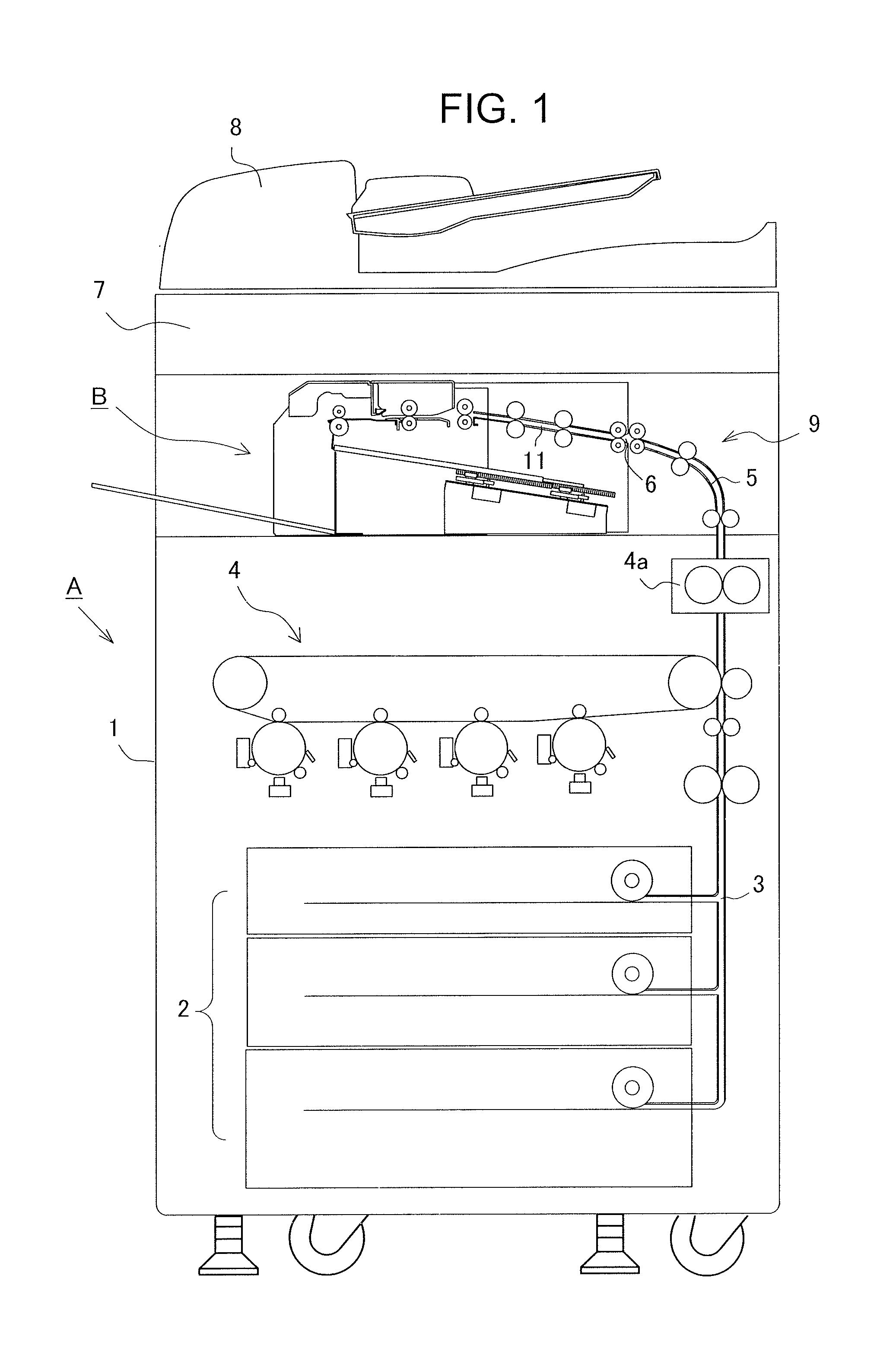
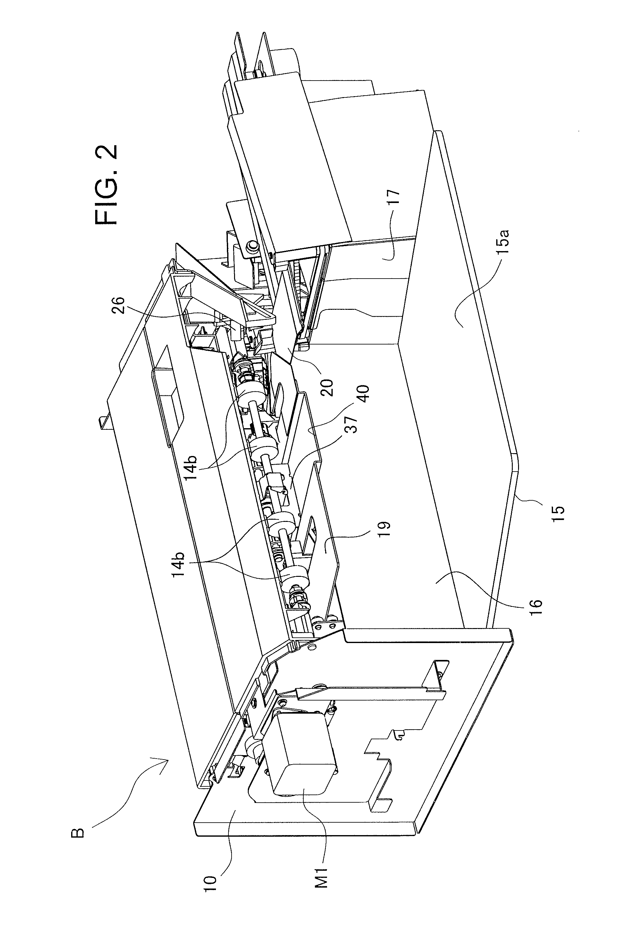
[0180]The sheet discharge rollers 14b are disposed in the sheet discharge outlet 13, and a sheet is carried out from the sheet carry-in path 11 in the center reference (which may be the side reference). Then, according to the print information, sheets are collected on the non-offset position and the offset position on the paper mount surface 15a. Embodiment 1 as shown in FIGS. 19A and 19B is the case of offsetting sheets to the right and left in the sheet-discharge orthogonal direction, and Embodiment 2 as shown in FIG. 20A is the case of offsetting sheets in front and back in the sheet discharge direction. Embodiment 3 as shown in FIG. 21A is to sort to a group (non-offset sheet discharge) in which sheets are directly stored on the paper mount surface 15a from the sheet discharge outlet 13, and another group (offset discharge) in which sheets are collected on the first and second support members 19, 20 from the sheet discharge outlet 13 while offsetting by a ...

embodiment 2

of the Offset Mechanism

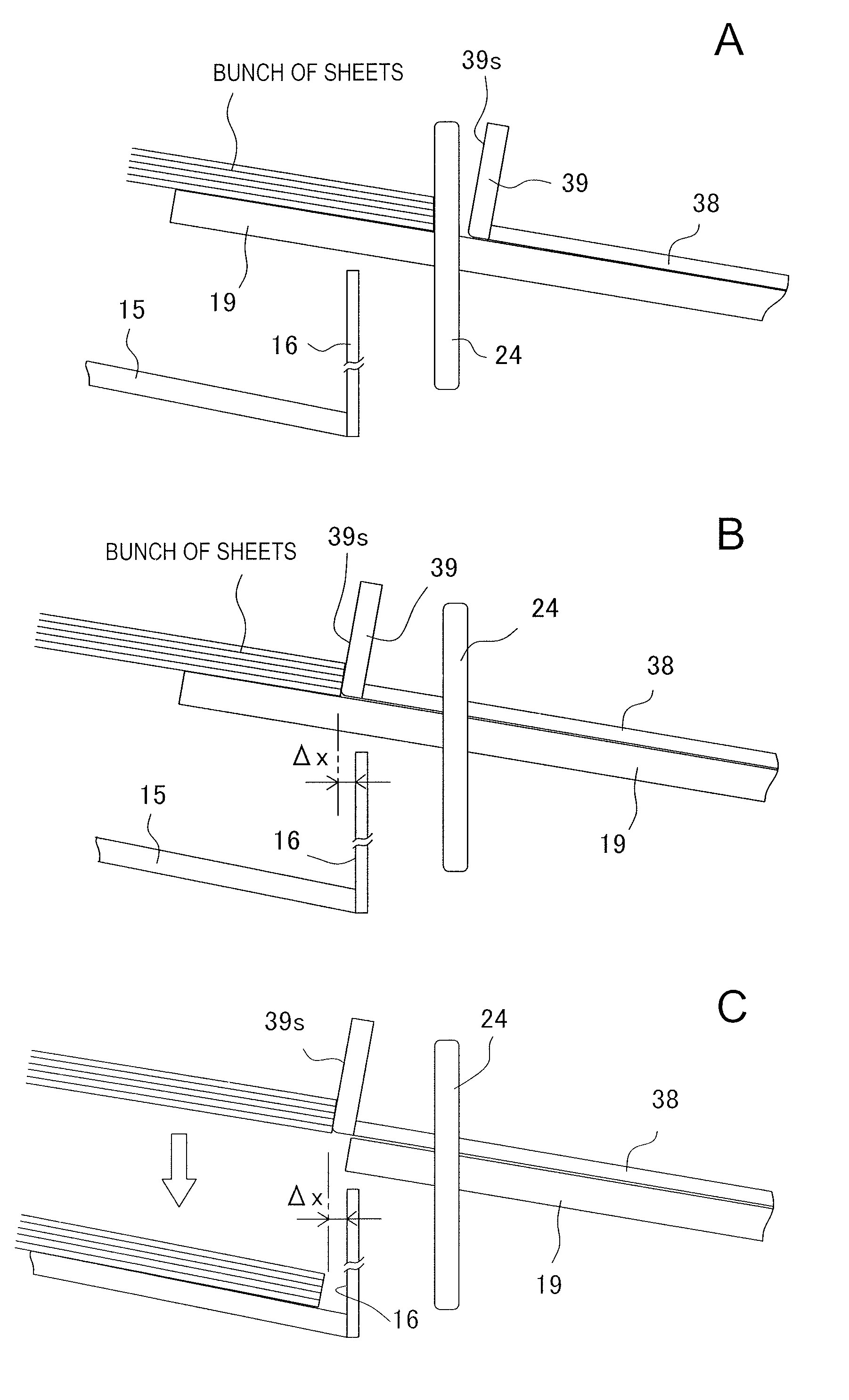
[0189]Embodiment 2 will be described next. In this Embodiment 2, as shown in FIGS. 20A and 20B, sheets are sorted into the non-offset position “nof” and offset position “of” in the sheet discharge direction to store. Therefore, as shown in FIGS. 20A and 20B, with the rear end (first) support member 19 and side edge (second) support member 20 positioned in the actuation positions above the paper mount surface 15a, sheets are collected on both support members from the sheet discharge outlet 13. At this point, the sheets are collected while the sheet side edge strikes the side edge regulation stopper 25 and the sheet rear end edge strikes the side end regulation stopper 24 by the aligning transport means 26 described below.

[0190]Then, when a job end signal is transferred from the image formation apparatus A, according to print job information from the image formation apparatus A, the sheet discharge means 50 selectively offsets bunches of sheets to the predetermi...


PUM

PropertyMeasurementUnit
Sheet carrier densityaaaaaaaaaa

Abstract

A paper mount surface is disposed while being inclined in the sheet discharge direction or sheet-discharge orthogonal direction, and first and second support members that support the sheet rear and portion in the sheet discharge direction and rear end portion are disposed to be able to shift between actuation positions inside the tray and retract positions. Then, after collecting sheets on both support members, the support member positioned in the direction orthogonal to the inclined direction of the paper mount surface is first retracted from above the tray, and next, the support member positioned in the inclined direction is retracted to the waiting position.

Description

BACKGROUND OF THE INVENTION[0001]1. Field of the Invention[0002]The present invention relates to a sheet storage apparatus that stores a sheet fed from an image formation apparatus or the like on a stack tray, and more particularly, to improvements in the sheet storage mechanism for enabling sheets to be stored neatly in a correct position on a paper mount surface having a height difference from a sheet discharge outlet.[0003]2. Description of the Related Art[0004]Generally, as this type of apparatus, such a stack mechanism is widely known that a stack tray is disposed on the downstream side of a sheet discharge path and that a sheet is dropped onto a paper mount surface having a height difference from the sheet discharge outlet to store. Then, such a post-processing mechanism is also known that a sub-tray is provided between the sheet discharge outlet and the paper mount surface to temporarily hold a sheet, the sheet undergoes post-processing such as binding processing, paper foldi...

Claims


Application Information

Patent Timeline
IPC IPC(8): B65H31/24B65H31/30
CPCB65H31/3009B65H31/24B65H31/02B65H31/3081B65H31/34B65H33/08B65H39/10B65H2301/4212B65H2404/152B65H2404/693B65H2405/113B65H2405/114B65H2801/27B65H31/32
Inventor SAITO, TAKEHIKOYAMANUSHI, SATOSHIAOYAGI, TATSUZOICHINOSE, YUICHI
Owner NISCA KK
Learn More