
Contactless power supplying device

a power supply device and contactless technology, applied in the direction of transformers, inductances, instruments, etc., can solve the problems of inability to determine whether a metal object is present or whether the relative positions are correct, the means for suppressing noise becomes complicated, and the metal detector may not accurately detect the presence of a metal foreign obj

Active Publication Date: 2014-04-17
PANASONIC INTELLECTUAL PROPERTY MANAGEMENT CO LTD
View PDF2 Cites 15 Cited by
  • Summary
  • Abstract
  • Description
  • Claims
  • Application Information

AI Technical Summary

Benefits of technology

The patent text describes a contactless power supplying device that uses electromagnetic induction to supply power to a power receiving device in an electric appliance. The device includes a primary coil and a secondary coil, with a basic power supplying unit circuit that excites the primary coil to supply secondary power through electromagnetic induction. The device also includes a detection circuit that detects a modulation wave generated by the secondary coil and demodulates it to determine if a metal foreign object is present. The device can accurately detect the presence of a metal foreign object, but it may also be affected by changes in the position of the primary and secondary coils. The patent text also describes a system control unit that determines if a metal foreign object is present and stops supplying power to the corresponding area. The technical effect of the invention is to provide a more accurate and reliable contactless power supplying device that can detect and prevent the presence of metal foreign objects.

Problems solved by technology

This results in a case in which it cannot be determined whether a metal object is present or whether the relative positions of the primary coil and secondary coil have changed.
Accordingly, the metal detector may not accurately detect the presence of a metal foreign object unless the primary coil and the secondary coil are correctly arranged to satisfy a positional relationship that is set in advance.
Thus, a means for suppressing the noise becomes complicated.

Method used


Image

  • Contactless power supplying device
  • Contactless power supplying device
  • Contactless power supplying device

Examples


Embodiment Construction

[0035]One embodiment of a contactless power supplying device according to the present invention will now be described with reference to the drawings.

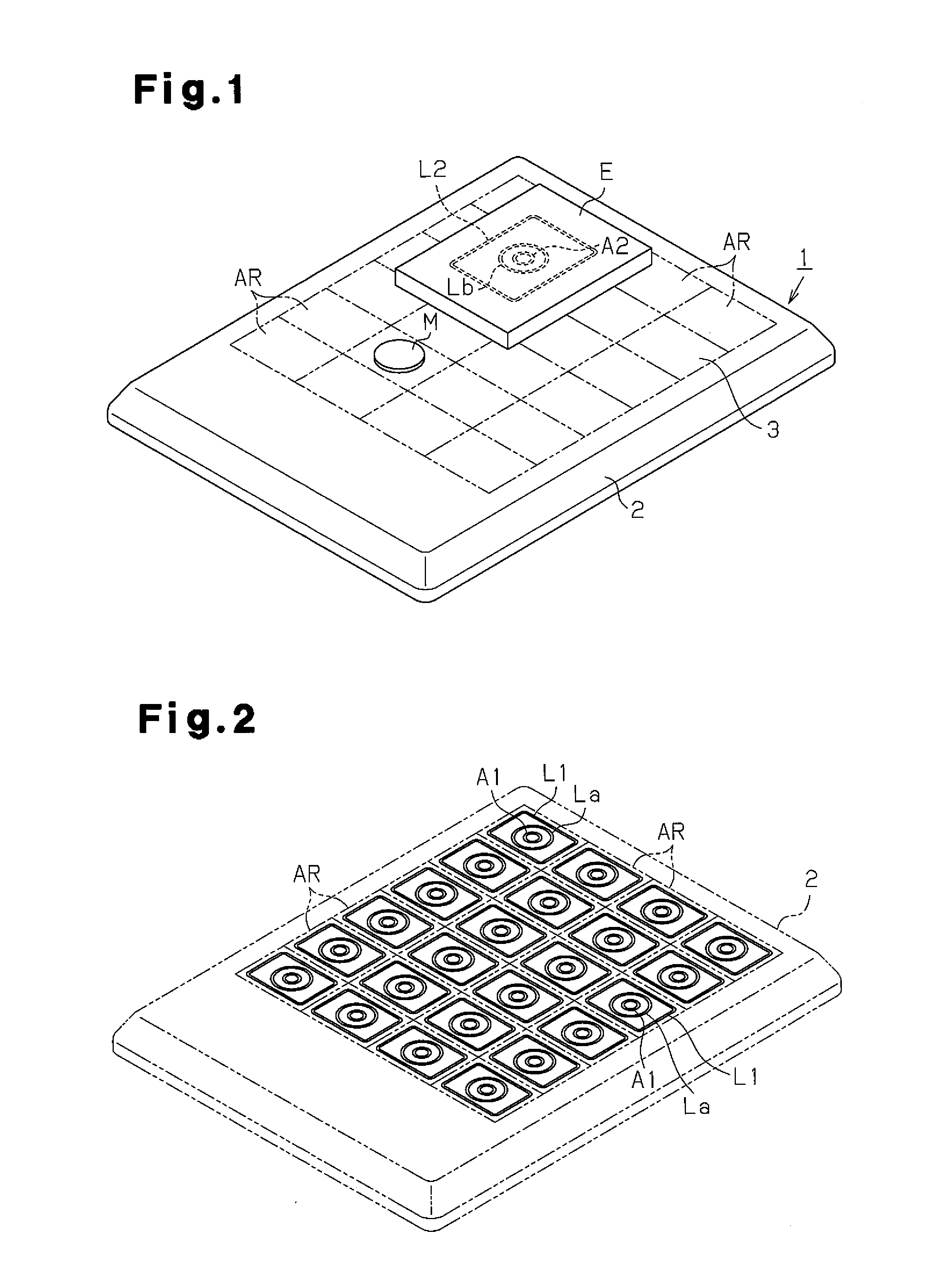
[0036]FIG. 1 is a perspective view entirely showing a contactless power supplying device (hereinafter simply referred to as the power supplying device) 1 and an electric appliance (hereinafter simply referred to as appliance) E, which is supplied with power from the power supplying device 1 in a contactless manner.

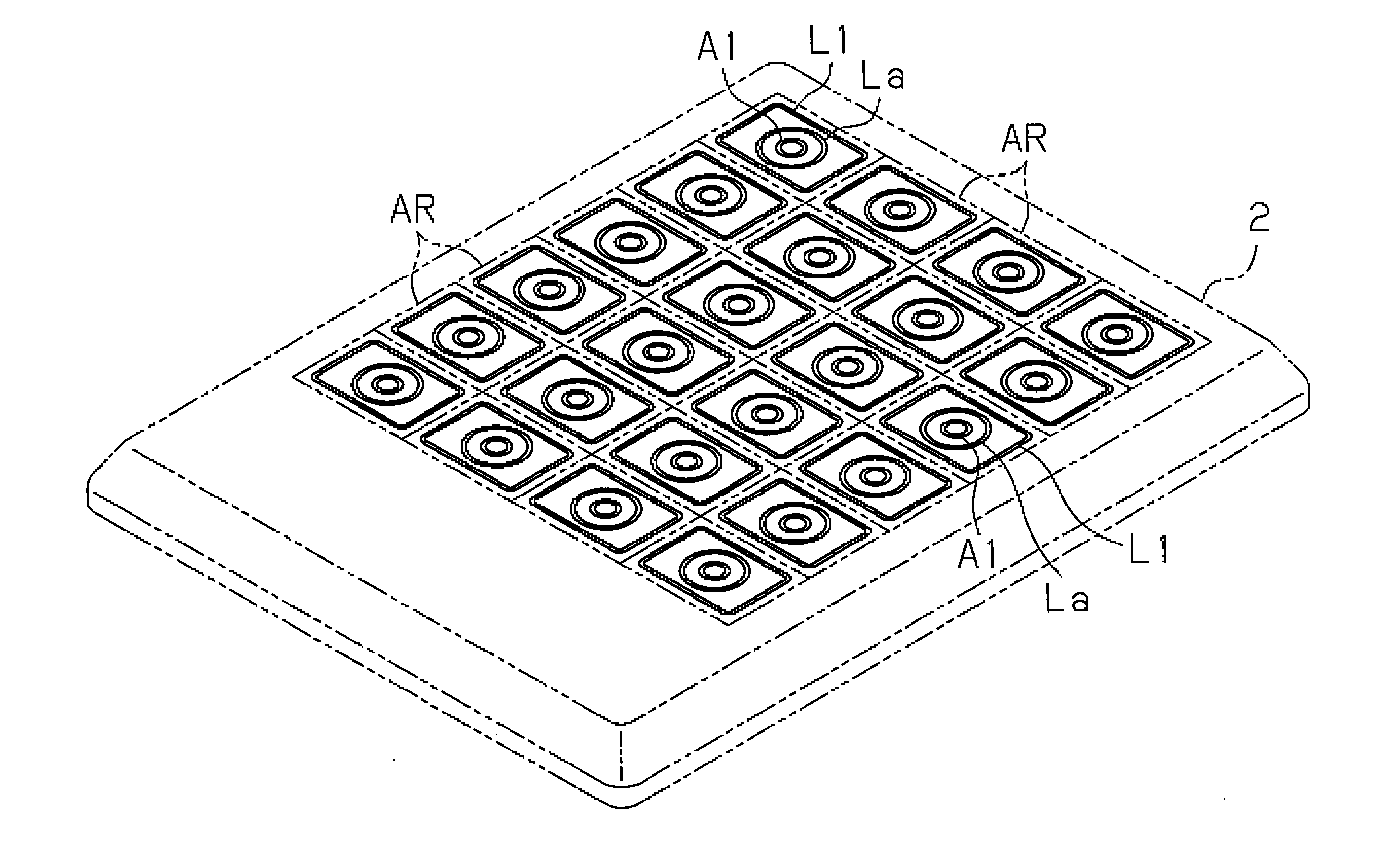
[0037]The power supplying device 1 includes a tetragonal plate-shaped frame 2, which has a planar upper surface that defines a setting surface 3 on which the appliance E is set. A plurality of square tetragonal supplying areas AR are defined in the setting surface 3. In the present embodiment, twenty-four power supplying areas AR, four from left to right and six from front to rear, are defined.

[0038]As shown in FIG. 2, a primary coil L1 wound to have a tetragonal shape in conformance with the contour of the power supplying are...


PUM


Abstract

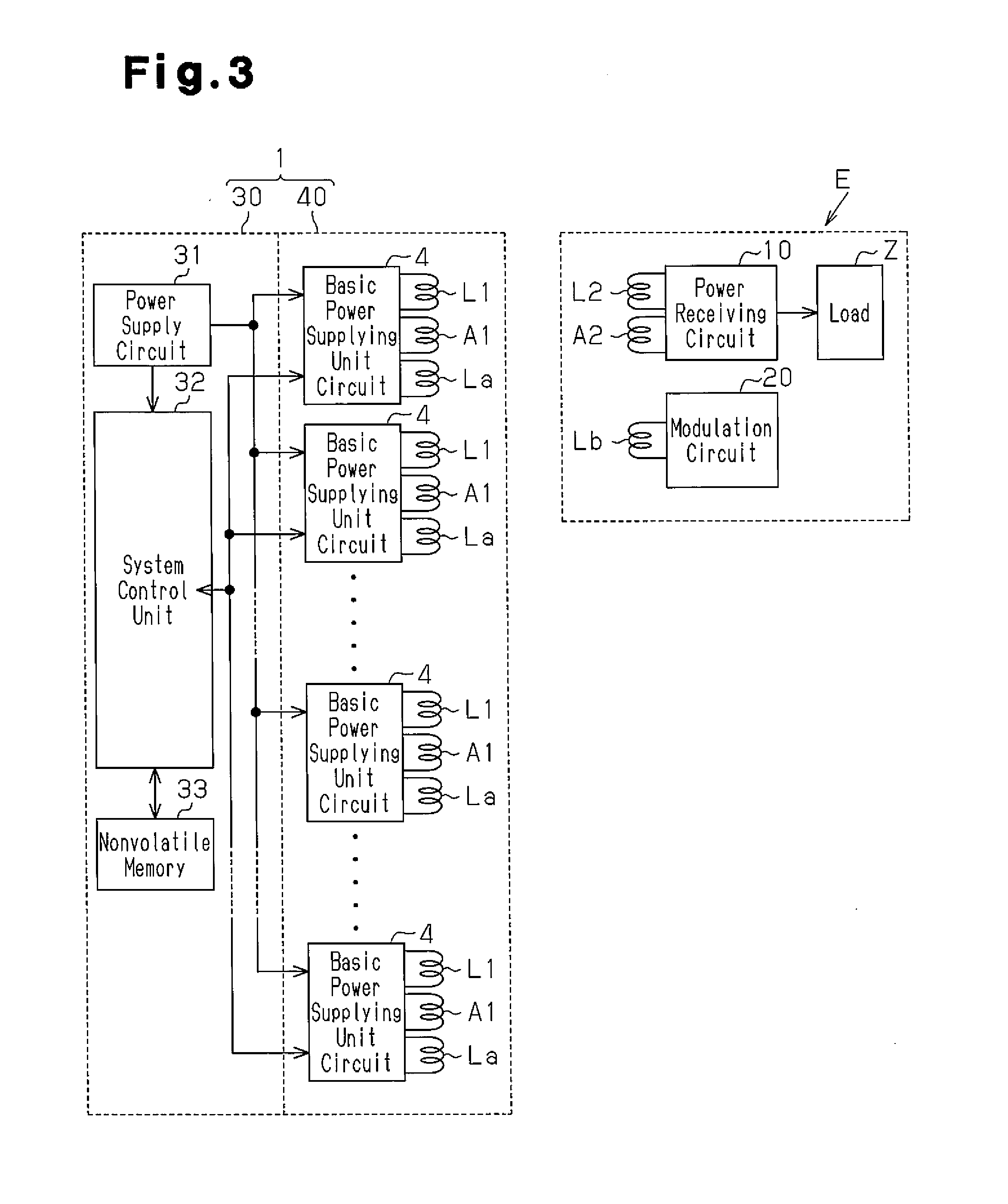
A contactless power supplying device is provided. A primary coil and a basic power supplying unit circuit are arranged in a power supplying area. The primary coil supplies secondary power through electromagnetic induction to a secondary coil of a power receiving device in the power supplying area. The basic power supplying unit circuit excites the primary coil in the power supplying area. The basic power supplying unit circuit transmits an oscillation signal from the power supplying area to the power receiving device, receives a modulated wave signal from the power receiving device that detects a modulation wave that is in accordance with a magnetic flux change, and detects the modulated wave signal to demodulate the modulation wave. A system control unit determines whether or not a metal foreign object is present in the power supplying area corresponding to the basic power supplying unit circuit based on the modulation wave.

Description

TECHNICAL FIELD[0001]The present invention relates to a contactless power supplying device.BACKGROUND ART[0002]In a contactless power supplying system that performs electromagnetic induction method, an electric appliance including a power receiving device is set on a setting surface of a contactless power supplying device. In this state, the contactless power supplying device excites its primary coil thereby exciting a secondary coil arranged in the power receiving device of the electric appliance through electromagnetic induction. Secondary power is generated by the secondary coil and converted into direct current power in the power receiving device. The DC power is supplied to a load of the electric appliance as driving power.[0003]The contactless power supplying device may include a metal detector that detects metal foreign objects and stops supplying power when the metal detector detects a metal foreign object. This prevents heating of a metal foreign object. When a metal foreig...

Claims


Application Information

Patent Timeline
IPC IPC(8): H01F38/14
CPCH01F38/14G01V3/105H02J7/0044H02J50/402H02J50/80H02J50/90H02J50/12H02J50/60H02J50/10
Inventor IRIE, KENICHIHYODO, SATOSHI
Owner PANASONIC INTELLECTUAL PROPERTY MANAGEMENT CO LTD
Learn More