Shielded ehf connector assemblies

a technology of shielded ehf and connectors, which is applied in the direction of solid-state devices, wireless communication, transmission, etc., can solve the problems of unwanted electromagnetic signal emissions and excessive electromagnetic emissions that may occur prior, and achieve the effect of reducing ehf signal leakag

Active Publication Date: 2014-04-17
MOLEX INC
View PDF5 Cites 12 Cited by
  • Summary
  • Abstract
  • Description
  • Claims
  • Application Information

AI Technical Summary

Benefits of technology

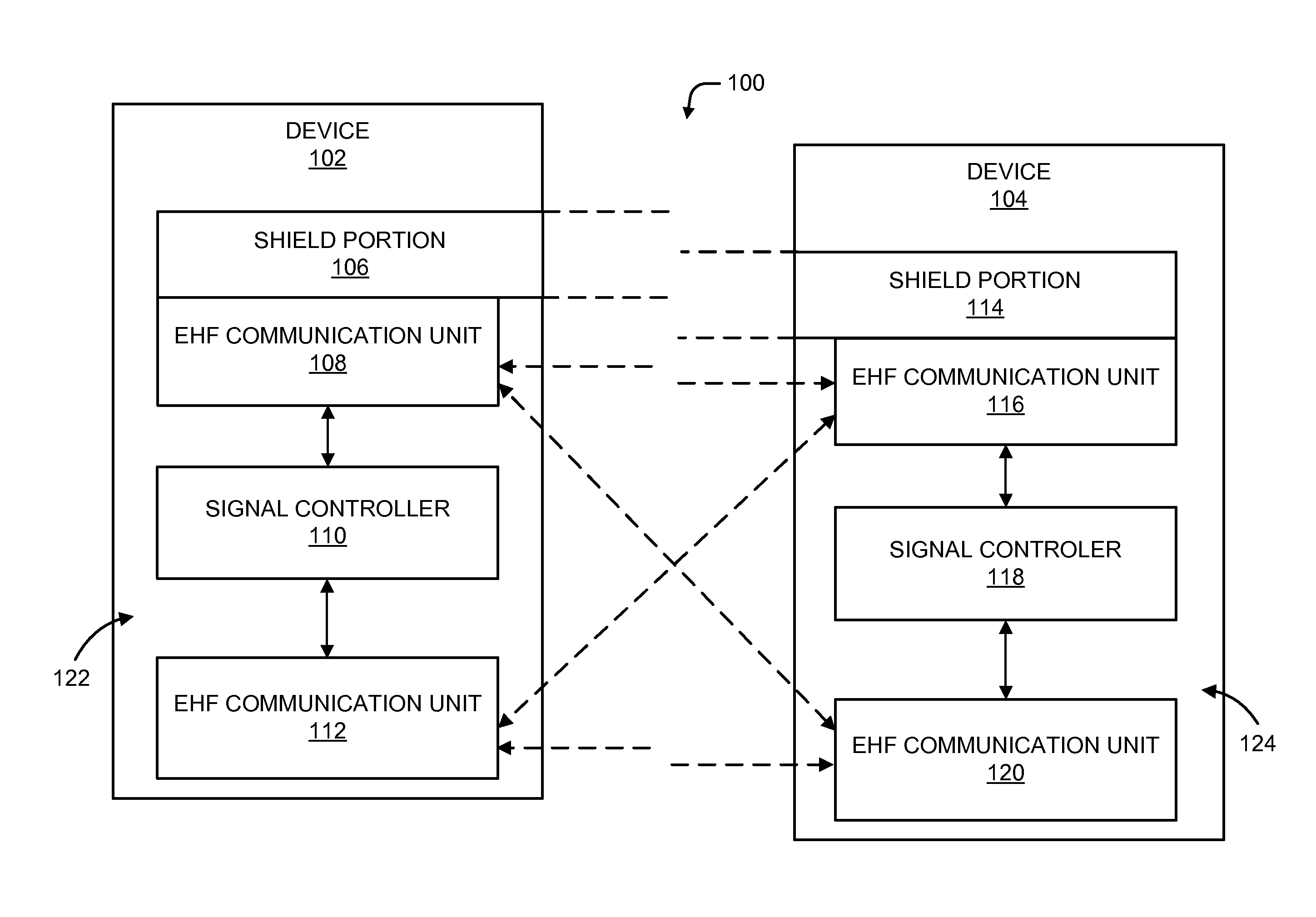
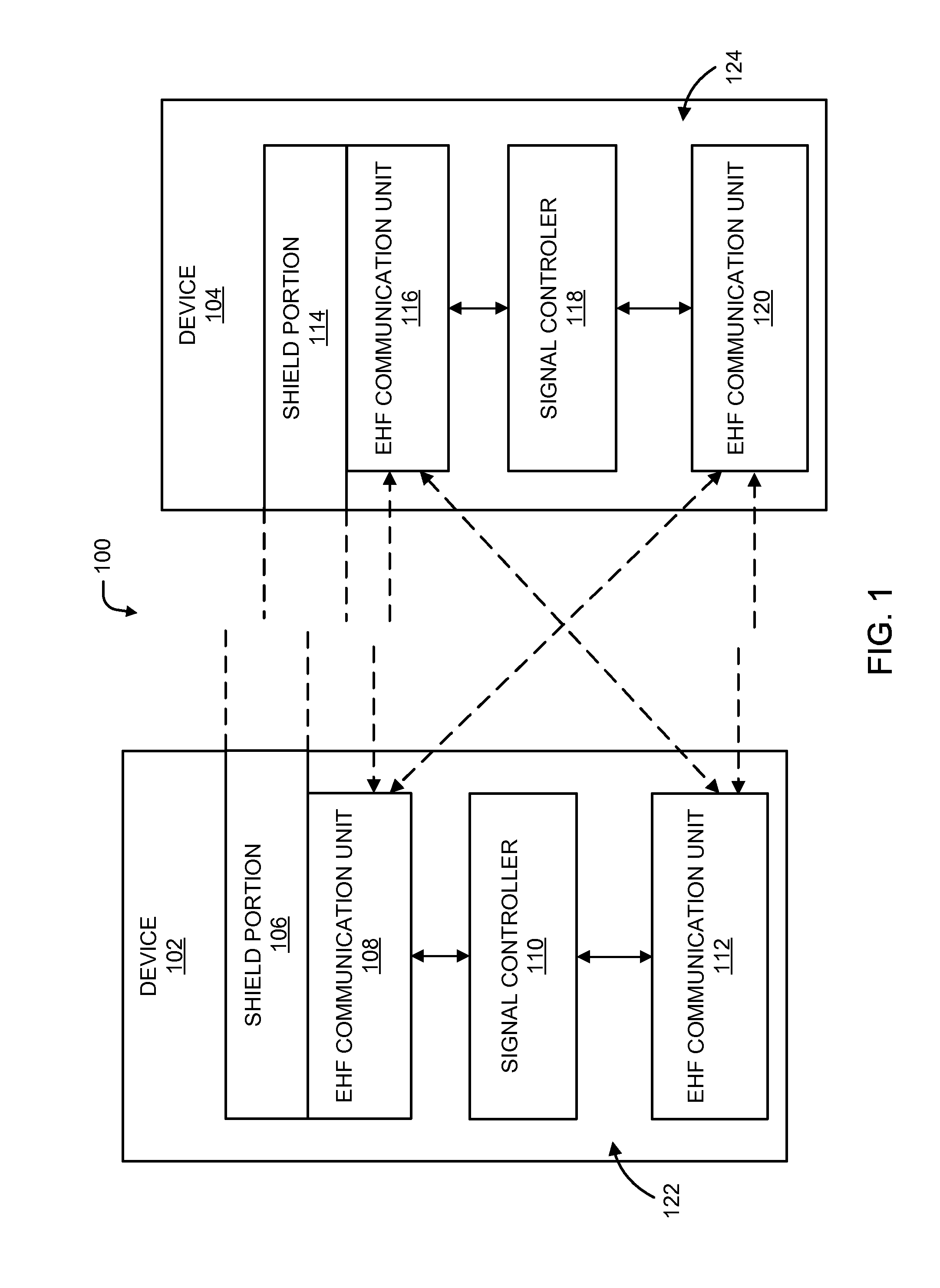
[0005]Shielded extremely high frequency (EHF) connector assemblies are disclosed herein. In some embodiments, a first extremely high frequency (EHF) shielded connector assembly is configured to be coupled with a second EHF shielded connector assembly. The first EHF connector assembly can include a first EHF communication unit operative to contactlessly communicate EHF signals with a respective first EHF communication unit included in the second EHF shielded connector assembly. The first connector can include a connector interface that includes a configuration to interface with a respective connector interface of the second EHF shield connector assembly, and several different material compositions that, in conjunction with the configuration of the connector, provides shielding to reduce EHF signal leakage when the first EHF assembly connector is coupled to the second EHF assembly connector and the first EHF communication unit is contactlessly communicating EHF signals with the respective first EHF communication unit.

Problems solved by technology

Such connector and backplane architectures introduce unwanted electromagnetic signal emissions that may interfere with other circuits and devices.
When wireless communication links are used, excessive electromagnetic emissions may occur prior to as well as during interconnection between two circuits or devices.

Method used


Image

  • Shielded ehf connector assemblies
  • Shielded ehf connector assemblies
  • Shielded ehf connector assemblies

Examples


Embodiment Construction

[0037]Illustrative embodiments are now described more fully hereinafter with reference to the accompanying drawings, in which representative examples are shown. Indeed, the disclosed communication system and method may be embodied in many different forms and should not be construed as limited to the embodiments set forth herein. Like numbers refer to like elements throughout.

[0038]In the following detailed description, for purposes of explanation, numerous specific details are set forth to provide a thorough understanding of the various embodiments. Those of ordinary skill in the art will realize that these various embodiments are illustrative only and are not intended to be limiting in any way. Other embodiments will readily suggest themselves to such skilled persons having the benefit of this disclosure.

[0039]In addition, for clarity purposes, not all of the routine features of the embodiments described herein are shown or described. One of ordinary skill in the art would readily ...


PUM


Abstract

Shielded extremely high frequency (EHF) connector assemblies are disclosed herein. In some embodiments, a first extremely high frequency (EHF) shielded connector assembly configured to be coupled with a second EHF shielded connector assembly. The first EHF connector assembly can include a first EHF communication unit operative to contactlessly communicate EHF signals with a second EHF communication unit included in the second EHF shielded connector assembly. The first connector can include a connector interface that includes a configuration to interface with a respective connector interface of the second EHF shield connector assembly, and several different material compositions that, in conjunction with the configuration, provide shielding to prevent or substantially reduce EHF signal leakage when the first EHF assembly connector is coupled to the second EHF assembly connector and the first EHF communication unit is contactlessly communicating EHF signals with the second EHF communication unit.

Description

RELATED APPLICATION[0001]This application is a continuation-in-part of U.S. patent application Ser. No. 13 / 754,694, filed Jan. 30, 2013. U.S. patent application Ser. No. 13 / 754,694 claims the benefit of U.S. Provisional Patent Application No. 61 / 592,491 filed Jan. 30, 2012. Each of the above-referenced patent applications is incorporated by reference in its entirety for all purposes.FIELD OF THE INVENTION[0002]The present disclosure relates to connectors for electronic devices and more specifically to systems and methods for controlling electromagnetic emissions in connectors connecting the electronic devices.BACKGROUND[0003]Advances in semiconductor manufacturing and circuit design technologies have enabled the development and production of integrated circuits (ICs) with increasingly higher operational frequencies. In turn, electronic products and systems incorporating such integrated circuits are able to provide much greater functionality than previous generations of products. Thi...

Claims


Application Information

Patent Timeline
Patent Type & Authority Applications(United States)
IPC IPC(8): H04B15/00H04W4/80
CPCH04B15/00H04B5/0031H01L2223/6677H01L2224/16225H01L2224/16245H01L2224/32225H01L2224/32245H01L2224/48227H01L2224/48247H01L2224/73265H01L2924/15311H01L2924/3011H01L2924/3025H01L2224/48091H01L2924/181H01L24/73H04W4/80H04W12/06H01L2924/00012H01L2924/00H01L2924/00014
Inventor MCCORMACK, GARY DISAAC, ROGER D.
Owner MOLEX INC
Why Eureka
Try Eureka