Video Laryngoscope With Disposable Blade

Active Publication Date: 2014-04-17
KARL STORZ GMBH & CO KG
View PDF8 Cites 14 Cited by
  • Summary
  • Abstract
  • Description
  • Claims
  • Application Information

AI Technical Summary

Benefits of technology

[0034]In certain embodiments, the channel in the blade is sandblasted for easier insertion/removal of the imager module, as less friction in the inside of the handle is created. In certain embodiments, the handle is sandblasted on the outside for a better grip.
[0035]In certain embodiments, the finger loop portion makes it easy for a user to manipulate the imager module. The finger loop makes it easier to remove the longitudinal member and prevents kinking of the cable during use. Moreover, the finger loop h

Problems solved by technology

However, these laryngoscope systems suffer from various deficiencies.
One problem known to laryngoscopes is that the imager shaft may become twisted when being inserted into a blade element.
If the imager shaft is not inserted correctly into the blade element, then the imager shaft may become stuck and the image produced by the

Method used


Image

  • Video Laryngoscope With Disposable Blade
  • Video Laryngoscope With Disposable Blade
  • Video Laryngoscope With Disposable Blade

Examples


Example

[0049]The following detailed description illustrates the invention by way of example, not by way of limitation of the principles of the invention. This description will enable one skilled in the art to make and use the invention, and describes several embodiments, adaptations, variations, alternatives and uses of the invention, including what is presently believed to be the best mode of carrying out the invention.

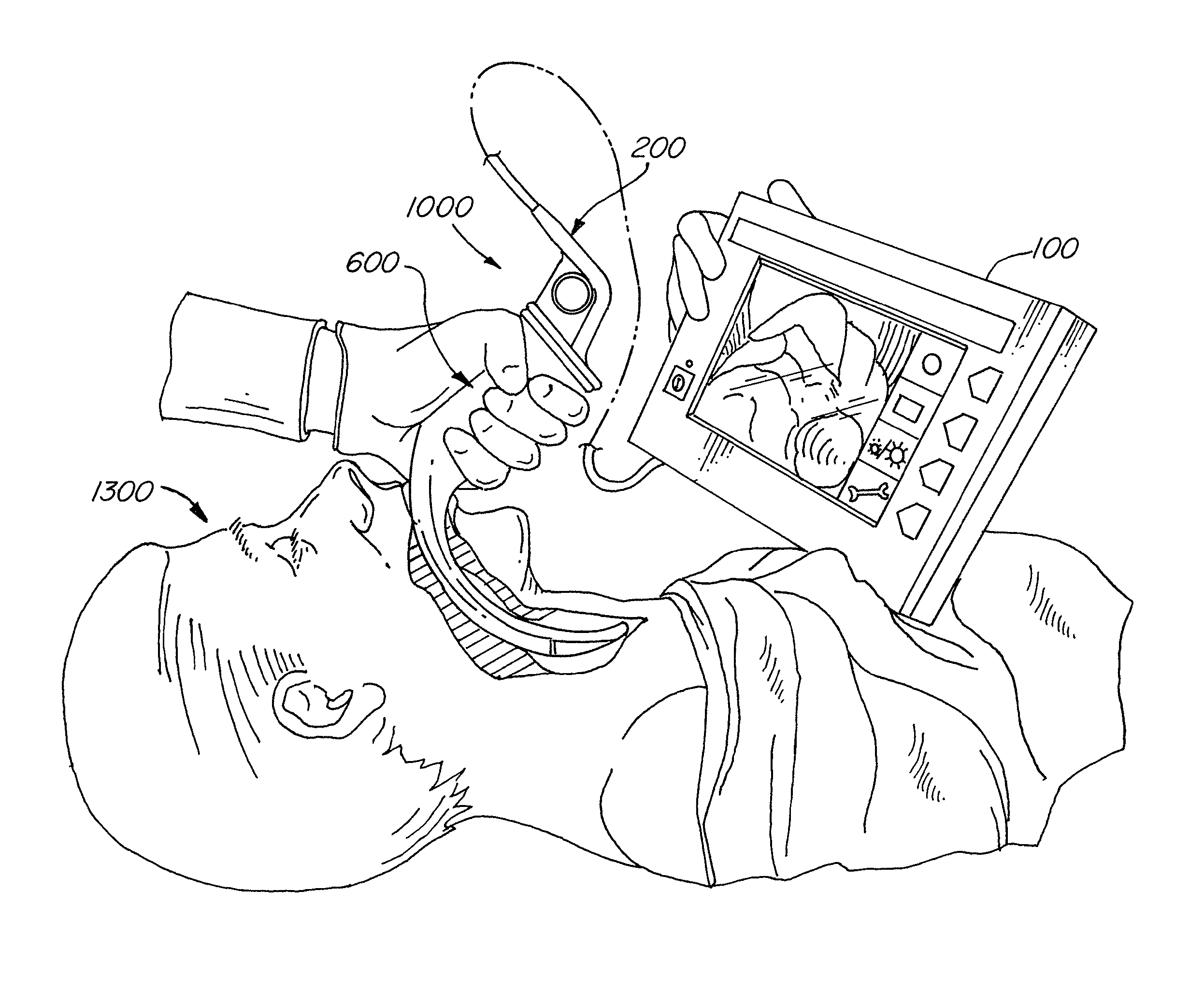
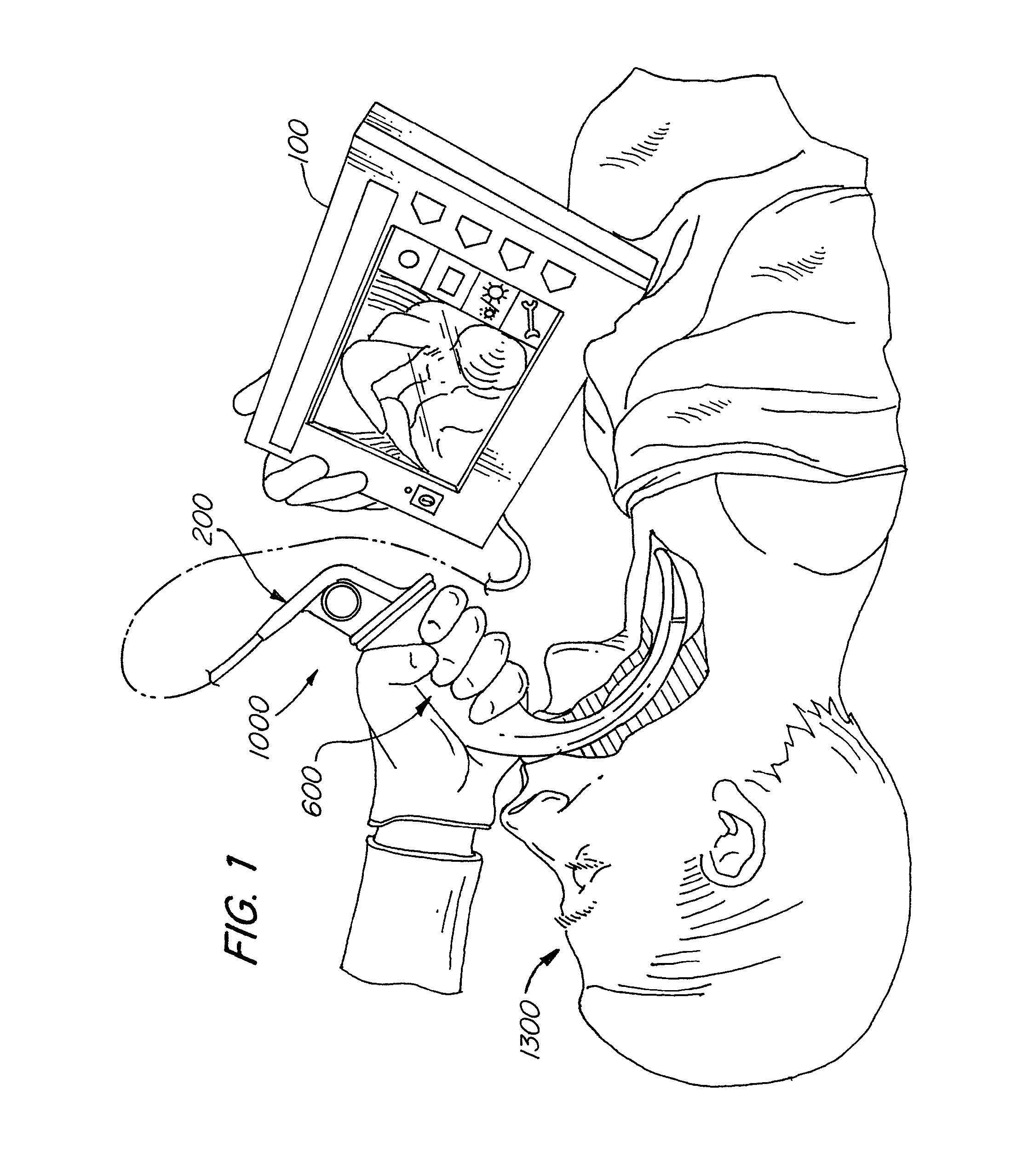
[0050]Referring to FIG. 1 a perspective view of intubation instrument 1000 is shown being used in a patient 1300. The intubation instrument 1000 is shown entering the patient 1300 through the patient's mouth. The intubation instrument 1000 extends just outside a patient's trachea, thus, providing views of a patient's trachea.

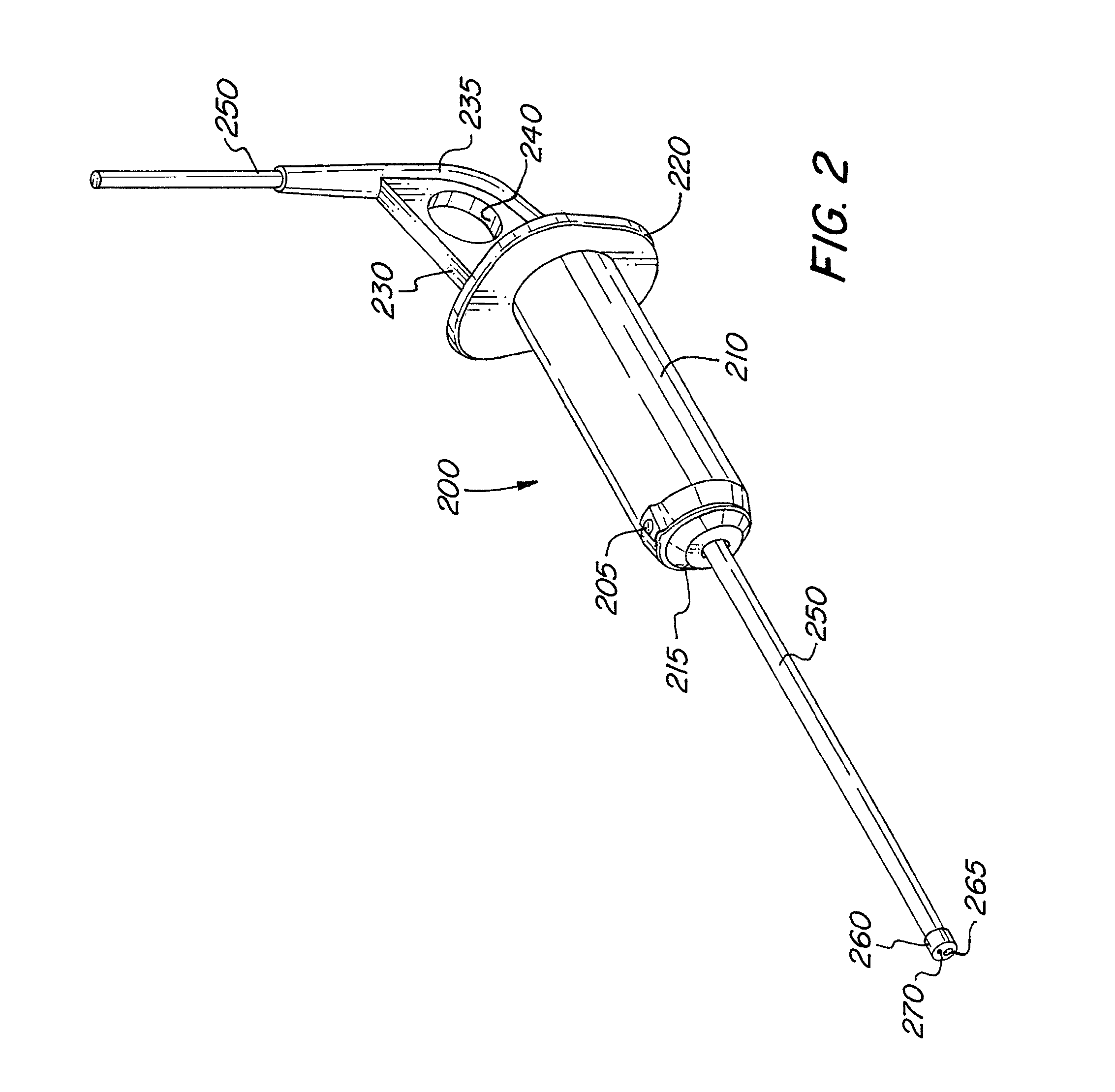
[0051]The intubation instrument includes blade 600 attached to imager module 200. The imager module 200 has a cable or electronic wiring that is connected to display 100. The display 100 may be a video monitor, computer, or other screen where an image p...


PUM


Abstract

An intubation instrument for intubating a patient's trachea including an imager module having a base unit with a finger loop and a longitudinal member attached to the distal end of the base unit, as well as a blade having a handle that is hollow and mates with the outer surface of the longitudinal member forming a male-female connection, the distal end of the blade projecting laterally therefrom, the distal end of the blade being insertable into a human during intubation.

Description

FIELD OF THE INVENTION[0001]This invention is directed to an intubation system and tools for intubation. The invention is particularly useful in various procedures for intubating a patient's trachea.BACKGROUND OF THE INVENTION[0002]Intubation instruments such as video laryngoscopes are known in the art. Known laryngoscope systems include U.S. Pat. No. 5,827,178 to Berall; U.S. Pat. No. 6,665,337 to Pacey; U.S. Pat. No. 6,543,447 to Pacey; U.S. Pat. No. 5,827,848 to Cubb et al.; Japanese Patent No. JP 2,292,504; U.S. Pat. No. 5,645,519 to Lee; U.S. Pat. No. 5,800,344 to Wood; U.S. Pat. No. 5,363,838 to George; U.S. Pat. No. 5,381,787 to Bullard; Crosby, Techniques using the Bullard Laryngoscope, Anesthesia and Analgesia 81: 1314-1315 (1995); WO 07 / 15144 to Shapiro; and U.S. Pat. No. 4,592,343 to Upsher.[0003]Known commercial laryngoscope systems include the Pentax AIRWAY SCOPE and the Verathon GLIDESCOPE RANGER. However, these laryngoscope systems suffer from various deficiencies.[00...

Claims


Application Information

Patent Timeline
IPC IPC(8): A61B1/267
CPCA61B1/267A61B1/00105A61B1/00142A61B1/05A61B1/0676A61B1/0684
Inventor HUELS, DIETERFUHR, EUGENIAMERZ, ULRICHRENNER, MARTINZIMMERLI, FABIAN
Owner KARL STORZ GMBH & CO KG
Why Eureka
Try Eureka