Integrally moulded plastic plug ring cap

Inactive Publication Date: 2020-02-27
MULLACKAL POLYMERS PTE LTD
View PDF0 Cites 0 Cited by
  • Summary
  • Abstract
  • Description
  • Claims
  • Application Information

AI Technical Summary

Benefits of technology

[0054]In a preferred embodiment disclosed hereof, there is provided an inventive integrally moulded plastic plug ring cap for sealing a container having an externally threaded neck thereon. Also disclosed is a method for forming said cap. The present inventor proposes to address at least majority of the shortcomings of state-of-art by advantageous implementation of a bi-injection moulding process wherein discrete thermoplastics are moulded sequentially for resulting correspondingly into a soft inner lip. Outer hard cap/shell is optionally provisioned with external knurling fo

Problems solved by technology

Process involved does away with more complex, costly, and

Method used


Image

  • Integrally moulded plastic plug ring cap
  • Integrally moulded plastic plug ring cap
  • Integrally moulded plastic plug ring cap

Examples


Example

EXAMPLE 1: PROTOCOL FOR PRODUCTION OF THE CRTESS CAP

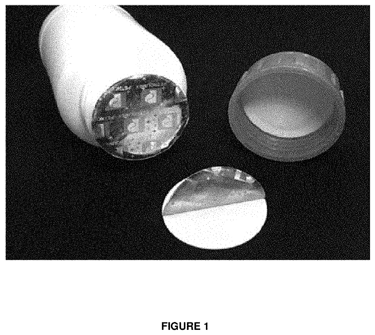
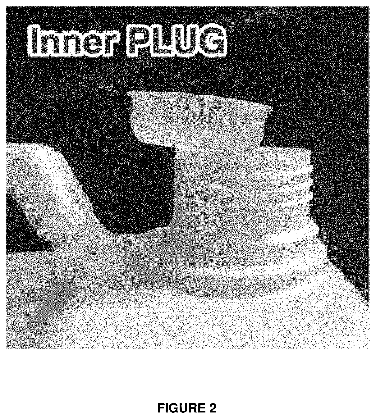
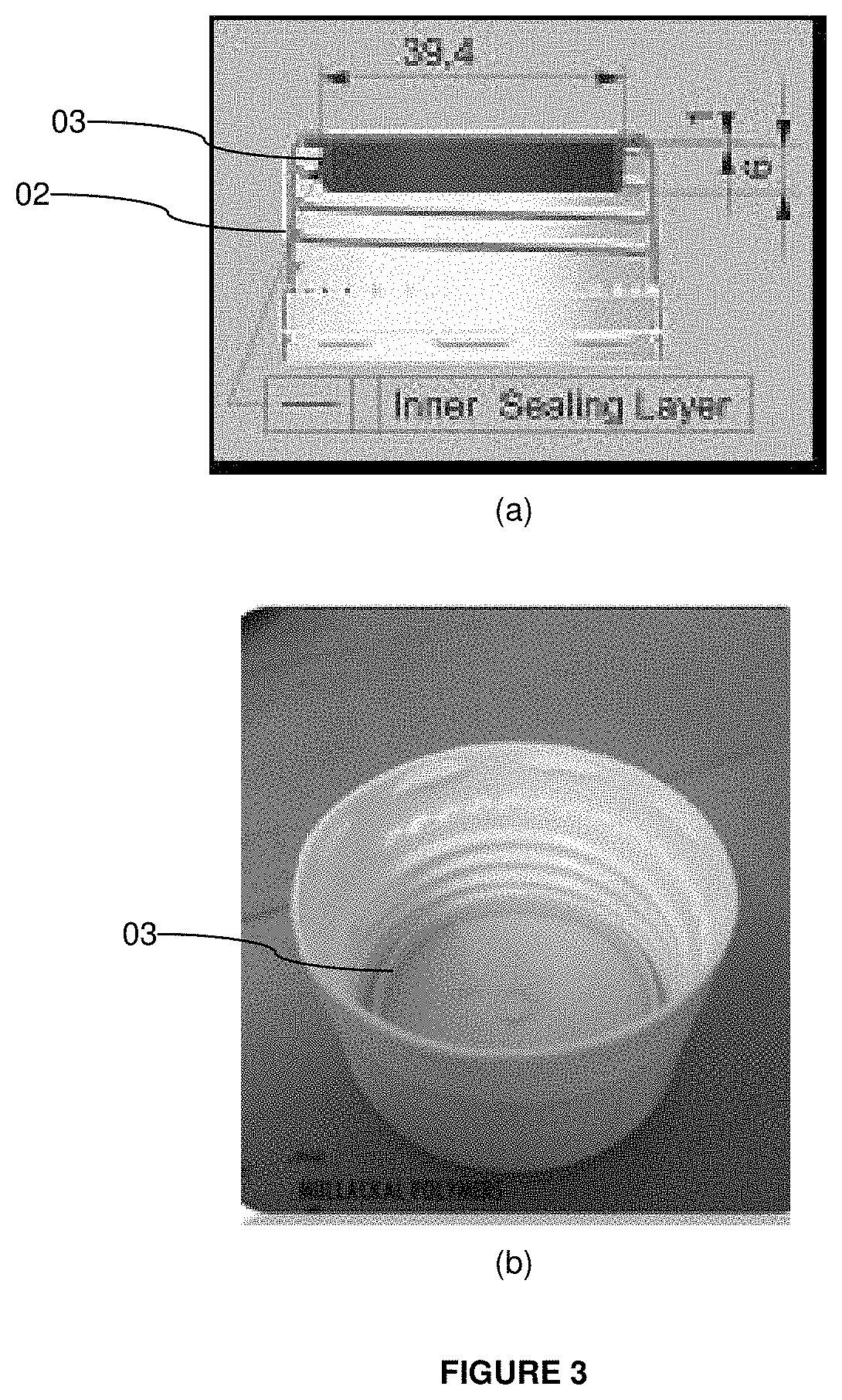
[0068]As mentioned in the foregoing disclosures, the CRTESS cap (01) proposed herein is prepared via a bi-injection moulding process wherein the inner plug ring (03) is molded first, and followed by molding of the outer shell (02).

[0069]According to one feature of the present invention evident from Example 1 above, the inner plug ring (03) is fused with the outer cap (02) during the molding process itself, hence the resulting CRTESS cap (01) has a single component / unibody construction. Hence no problems are experienced as otherwise such as wads jumping out of the caps or being displaced out of position observed in prior art solutions. FIG. 5 (a) to (d) are top view, isometric view, side view, front view, and bottom views respectively of the final product, that is the CRTESS cap (01) made according to the disclosures hereof.

[0070]In a preferred embodiment, a plastic HPDE cap is maintained during moulding at an increased temperature ...

Example

EXAMPLE 2: TESTING OF THE CRTESS CAP

[0071]a) Drop test: The CRTESS cap made using the protocol of Example 1 was received via screw fit at mouth of a liquid filled bottle. Said bottle with CRTESS cap was dropped from various heights. Here, it was observed that the bottle with CRTESS cap neither ruptures nor leakage was observed from the bottle. This concludes that the CRTESS cap successfully cleared the standard drop test applicable for articles of its nature.[0072]b) Leakage test: The CRTESS cap made using the protocol of Example 1 was received via screw fit at mouth of a liquid filled bottle. Said bottle with CRTESS cap was subjected to an air pressure of 20 kPa for 5 min. Here, it was observed that the bottle with CRTESS cap neither ruptures nor leakage was observed from the bottle or said cap. This concludes that the CRTESS cap successfully cleared the standard leakage test applicable for articles of its nature.[0073]c) Hydraulic test: The CRTESS cap made using the protocol of Ex...

Example

EXAMPLE 3: ALTERNATIVE VARIANTS OF THE CRTESS CAP

[0075]The CRTESS cap proposed herein may be produced in alternative versions depending on the specific use-case and application intended. The following versions are few non-limiting examples in this line-a)[0076]a) CRTESS Cap with a vent plug insertion option and self-sealing: As seen in the accompanying FIG. 7 (a) to (c), provision is made in the CRTESS cap itself to insert a vent plug (011). The vent plugs are third party sourced components comprising a plastic plug with a membrane inside. The membrane doesn't allow liquid to pass only air to pass. Hence any pressure difference which occurs inside the container is solved by the vent plug. In this variant of the CRTESS cap, the inventor named herein has made a provision such that the vent plug can be directly inserted into the CRTESS cap (this is unconventional as usually such vent plugs are inserted into the inner plug or comes as a part of the sealing wad)[0077]b) CRTESS Cap with c...


PUM


Abstract

A screw cap produced by a bi-injection moulding process is disclosed herein in which discrete thermoplastics are moulded sequentially for resulting correspondingly into a soft inner lip and outer hard shell for sealing containers or conduits having an externally threaded neck, said containers or conduits being directed at holding or conveying chemical, food, and pharmaceutical preparations.

Description

FIELD OF THE INVENTION[0001]This invention relates generally to articles made of formable materials. More particularly, this invention relates to the inventive construction, methods of preparation and use of a chemical-resistant, leak-proof, tamper-evident, self-sealing, integrally moulded closure for use in conjunction with containers employed predominantly in the chemical, food, and pharmaceutical industries.BACKGROUND OF THE INVENTION AND DESCRIPTION OF RELATED ART[0002]Advantages of plastic, majorly the ease of formability, lighter weight, ability to form thin-walled yet resilient structures, thermal and electrical insulating properties, appealing aesthetics, chemical inertness, ease of sterilization, decreased breakage, recyclability and lower costs as compared to glass, steel or other comparable materials have made them increasingly popular in the packaging industry. Prime examples of such plastics are virgin PET, PP, and HDPE which have been approved by the Food and Drug Admi...

Claims


Application Information

Patent Timeline
IPC IPC(8): B65D41/04
CPCB65D41/0442B65D2101/0023B65D41/0414B65D41/325B65D41/3409B65D51/1616B65D2401/15
Inventor PILLAI, RAMESH
Owner MULLACKAL POLYMERS PTE LTD
Why Eureka
Try Eureka