Piston for an air pump

a technology of air pump and piston seat, which is applied in the direction of machines/engines, liquid fuel engines, positive displacement liquid engines, etc., can solve the problems of poor working efficiency of the piston seat, warping and deformation of the elastic flap, and complex combination between the elastic flap and the piston seat, etc., to reduce operating noise, reduce operating noise, and easy to install

Active Publication Date: 2014-03-06
WANG WEI CHI
View PDF4 Cites 0 Cited by
  • Summary
  • Abstract
  • Description
  • Claims
  • Application Information

AI Technical Summary

Benefits of technology

[0011]An objective of the invention is to provide a piston for an air pump being easy to install, having a low cost and reducing operating noise.

Problems solved by technology

1. The elastic flap is mounted on the piston seat by a rivet, so the combination between the elastic flap and the piston seat is complex.
Moreover, the elastic flap becomes warped and deformed when the air pump has been used for a period.
Thus, the working efficiency of the piston is poor.
2. The elastic flap is metal and causes a noise when the elastic flap returns to cover the through hole of the piston seat.
3. The material cost of the elastic flap is high.

Method used


Image

  • Piston for an air pump
  • Piston for an air pump
  • Piston for an air pump

Examples


Embodiment Construction

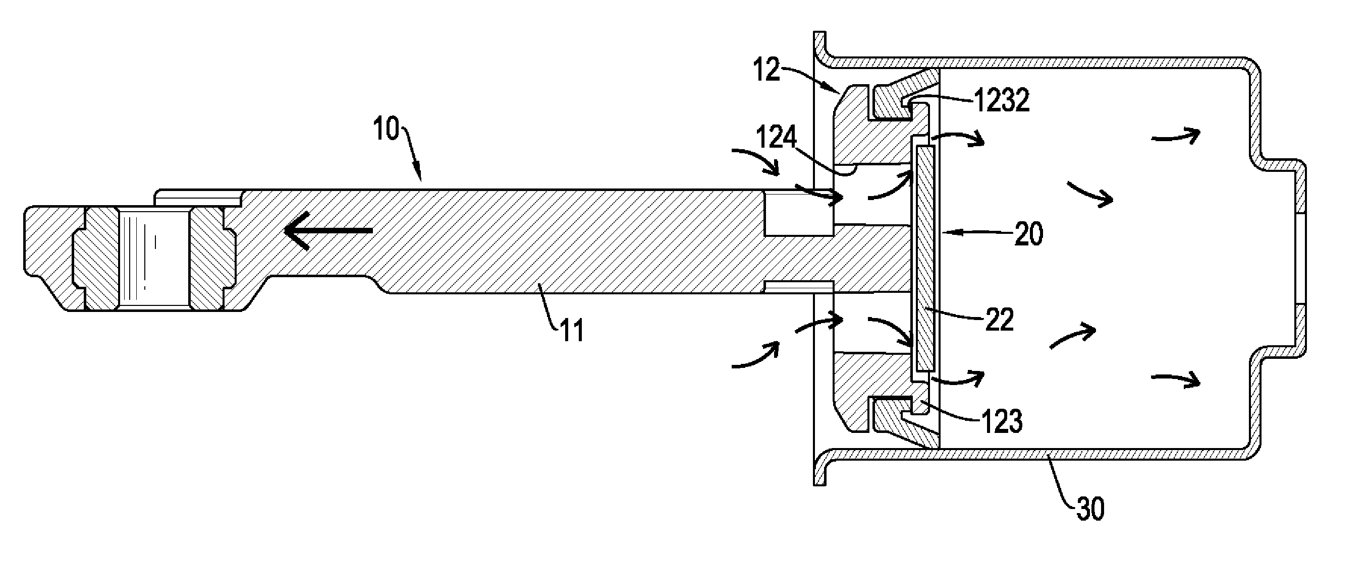
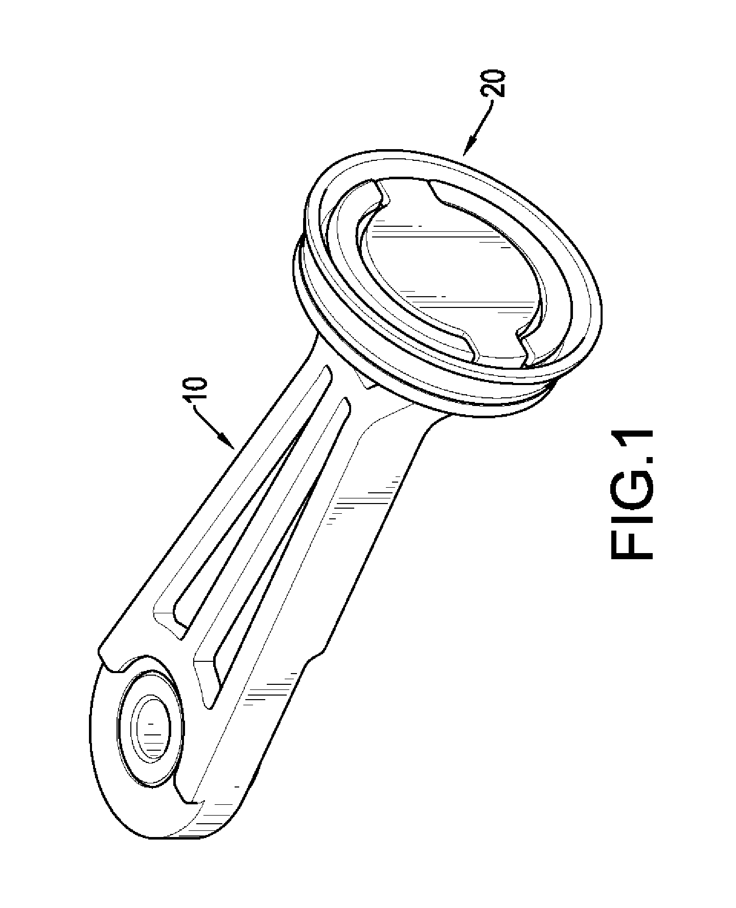
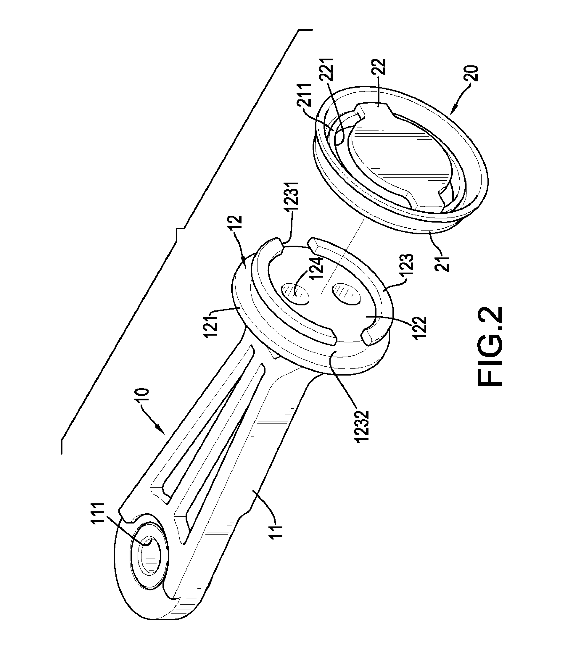
[0023]With reference to FIGS. 1 to 3, a piston for an air pump in accordance with the present invention comprises a connecting rod 10 and a sealing valve 20.

[0024]With reference to FIGS. 2 and 3, the connecting rod 10 has a seat 12 and a rod body 11. The seat 12 has a first surface, a second surface, a base 121, a protrusion 122, multiple engaging flanges 123, a through hole 124, a groove 1232 and a retaining surface. The second surface is opposite to the first surface. The base 121 is disc-shaped and has a connecting surface. The second surface is defined in the base 121 and is opposite to the connecting surface. The protrusion 122 is cylindrical and protrudes from the connecting surface of the base 121. The first surface is defined in a front end of the protrusion 122. The engaging flanges 123 are respectively formed on and protruding from the protrusion 122 at an edge of the protrusion 122 to form the groove 1232 defined between the base 121 and the engaging flanges 123 and aroun...


PUM


Abstract

A piston for an air pump has a connecting rod and a sealing valve. The connecting rod has a seat. The seat has a groove and a retaining surface. The groove is defined in an outer surface of the seat. The retaining surface is adjacent to the groove. The sealing valve movably engages the seat of the connecting rod and has an engaging ring and a sealing part. The engaging ring has an inwall which extends into the groove and has an engaging surface facing the retaining surface. The sealing part is connected with the inwall of the engaging ring and sealingly covers the through hole. The sealing valve is not prone to deformation and warpage during the operation of the piston to prevent any operating noise problem.

Description

BACKGROUND OF THE INVENTION[0001]1. Field of the Invention[0002]The invention relates to a piston for an air pump, and more particularly to a piston for an air pump to enhance the sealing effect, to prevent deformation of a valve and to reduce operating noise.[0003]2. Description of Related Art[0004]An air pump for inflating tires or airbeds generally comprises a motor, a piston cylinder and a piston. The piston reciprocates in the piston cylinder by operation of the motor, and the piston can compress the air in the piston cylinder to high pressure gas for inflation.[0005]The piston has a piston seat and an elastic flap. The piston seat is mounted at a top end of the piston and has a through hole. The elastic flap is mounted on a top end of the piston seat and covers the through hole. When the piston is driven by the motor, the airflow impacts the elastic flap to lift the elastic flap from the through hole, and then the airflow flows through the through hole into the piston cylinder...

Claims


Application Information

Patent Timeline
Patent Type & Authority Applications(United States)
IPC IPC(8): F16J1/09
CPCF16J1/09F04B39/0016F04B53/12F04B53/127F16J1/12
Inventor WANG, WEI-CHI
Owner WANG WEI CHI
Why Eureka
Try Eureka