Scroll type fluid machine, method and device for forming elastic coating thereon

a fluid machine and roller technology, applied in the direction of liquid fuel engines, machines/engines, rotary piston liquid engines, etc., can solve the problems of difficult to obtain optimum coating thickness, difficult to precisely control the coating thickness of the coating layer, and difficult to obtain precise coating thickness. , to achieve the effect of reducing seizure, contact damage, and reducing the number of strokes

Inactive Publication Date: 2013-11-14
ANEST IWATA CORP
View PDF7 Cites 1 Cited by
  • Summary
  • Abstract
  • Description
  • Claims
  • Application Information

AI Technical Summary

Benefits of technology

[0019]In consideration of these problems in the related art, a first object of the present invention is to enable formation of a coating layer with which a tightly sealed enclosed space is formed between a fixed scroll and an orbiting scroll without the need for precise control of a coating thickness and seizure, galling, wear, contact damage, and the like do not occur between wrap side faces. A second object of the present invention is to realize a coating formation device with which an even and highly precise coating thickness can be obtained easily over an entire lengthwise direction of a wrap portion.
[0043]Hence, at low cost, the enclosed space of the scroll type fluid machine can be sealed more tightly, and galling, wear, damage, and the like between the wrap portions can be suppressed. As a result, an operating efficiency of the scroll type fluid machine can be improved.

Problems solved by technology

However, Patent Documents 1 to 4 do not disclose a method of precisely controlling the coating thickness of the coating layer.
In the coating method disclosed in Patent Document 2, the coating is handled in an unhardened state, making it difficult to obtain a precise coating thickness.
The clearance between the wrap side faces must therefore be measured in each region, and an optimum coating thickness is not always obtained during an operation.
Moreover, it is not easy to apply the coating layer at an even coating thickness in a lengthwise direction of the wrap side face, and yet none of Patent Documents 1 to 4 discloses a method of making this possible.

Method used


Image

  • Scroll type fluid machine, method and device for forming elastic coating thereon
  • Scroll type fluid machine, method and device for forming elastic coating thereon
  • Scroll type fluid machine, method and device for forming elastic coating thereon

Examples


first embodiment

(First Embodiment)

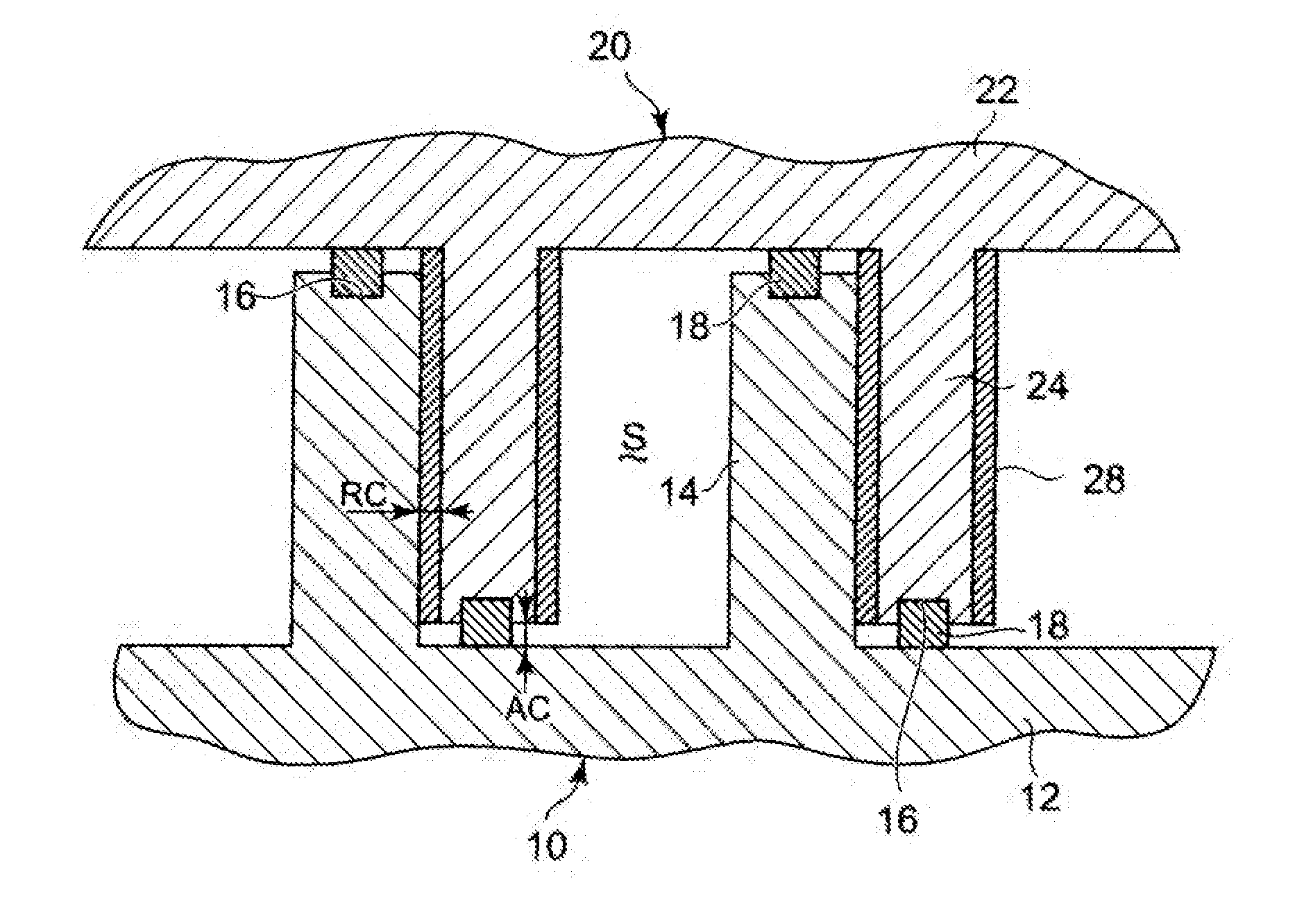
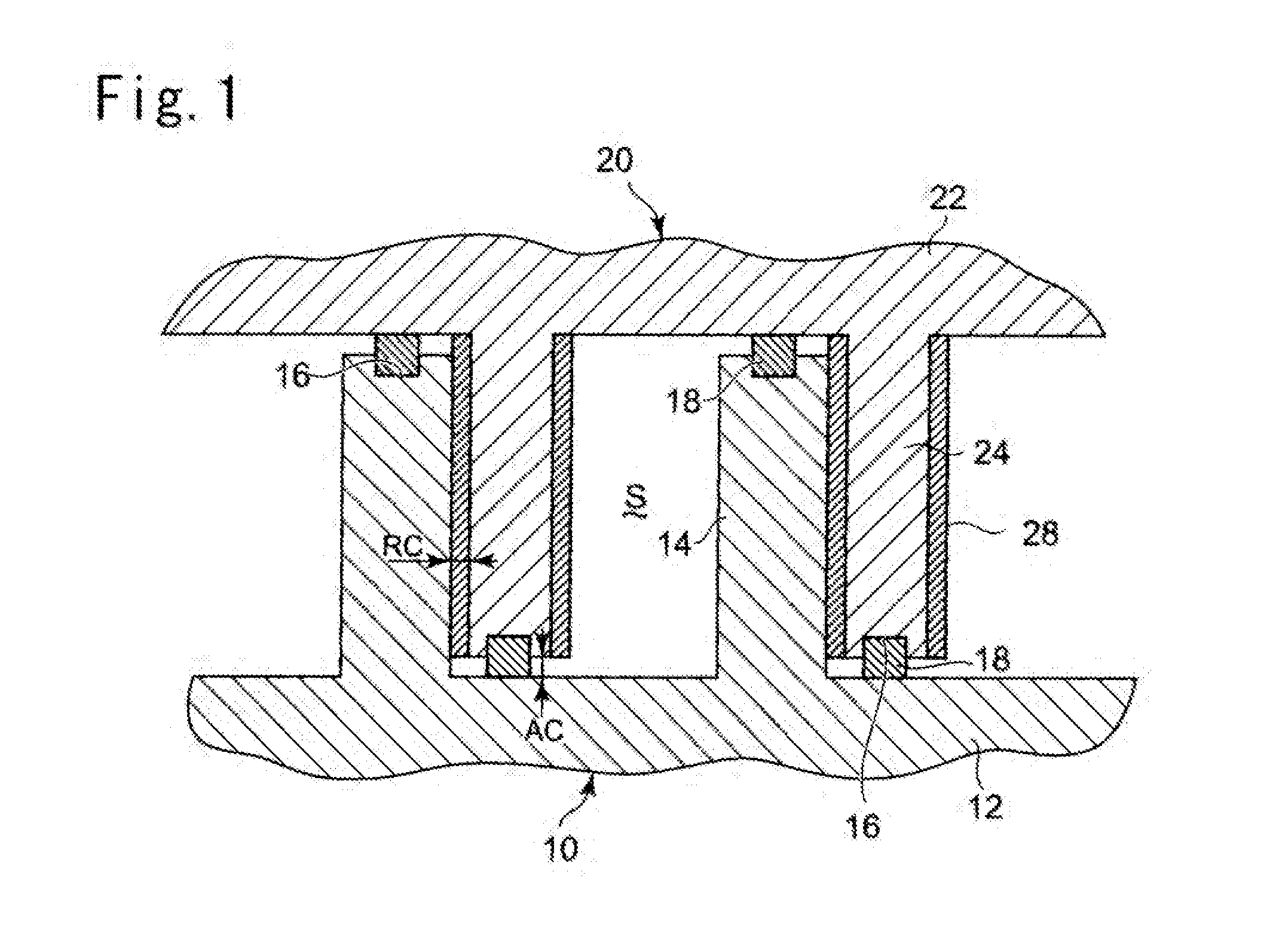
[0053]A first embodiment of a scroll type fluid machine and a method and a device for forming an elastic coating thereon according to the present invention will now be described on the basis of FIGS. 1 to 4. FIG. 1 shows a meshing portion between a fixed scroll 10 and an orbiting scroll 20 of a non-lubricated scroll type air compressor. In FIG. 1, the aluminum fixed scroll 10 is constituted by a disc-shaped end plate 12 and a spiral wrap portion 14 that stands upright from the end plate 12 in a right-angle direction. The aluminum orbiting scroll 20 is similarly constituted by a disc-shaped end plate 22 and a spiral wrap portion 24 that stands upright from the end plate 22 in a right-angle direction.

[0054]Spiral recessed grooves 16 are engraved in respective end surfaces of the wrap portions 14 and 24, and spiral tip seals 18 are fitted tightly into the recessed grooves 16. A clearance AC between the respective end plates 12, 22 and the respective wrap portions 14, ...

examples

[0068]A scroll type air compressor including the elastic coating 28 having the components and composition described above on one side face of the wrap portion 24 was operated, whereupon a damaged condition of the wrap portion 24 and a sealing condition between the wrap portion side faces were inspected. Results are shown in FIG. 4. In the inspection, the clearance RC between the wrap portion side faces of the fixed scroll 10 and the orbiting scroll 20 was changed variously, the elastic coating 28 was formed at different coating thicknesses by performing the coating formation process described above in accordance with the clearances RC, and the inspection was performed using the formed elastic coatings 28.

[0069]It is evident from FIG. 4 that when the elastic coating 28 is between 30 and 80 μm, contact between the opposing wrap portions 24 is alleviated, and therefore damage to the wrap portions can be prevented and a favorable sealing condition can be maintained between the wrap port...

second embodiment

(Second Embodiment)

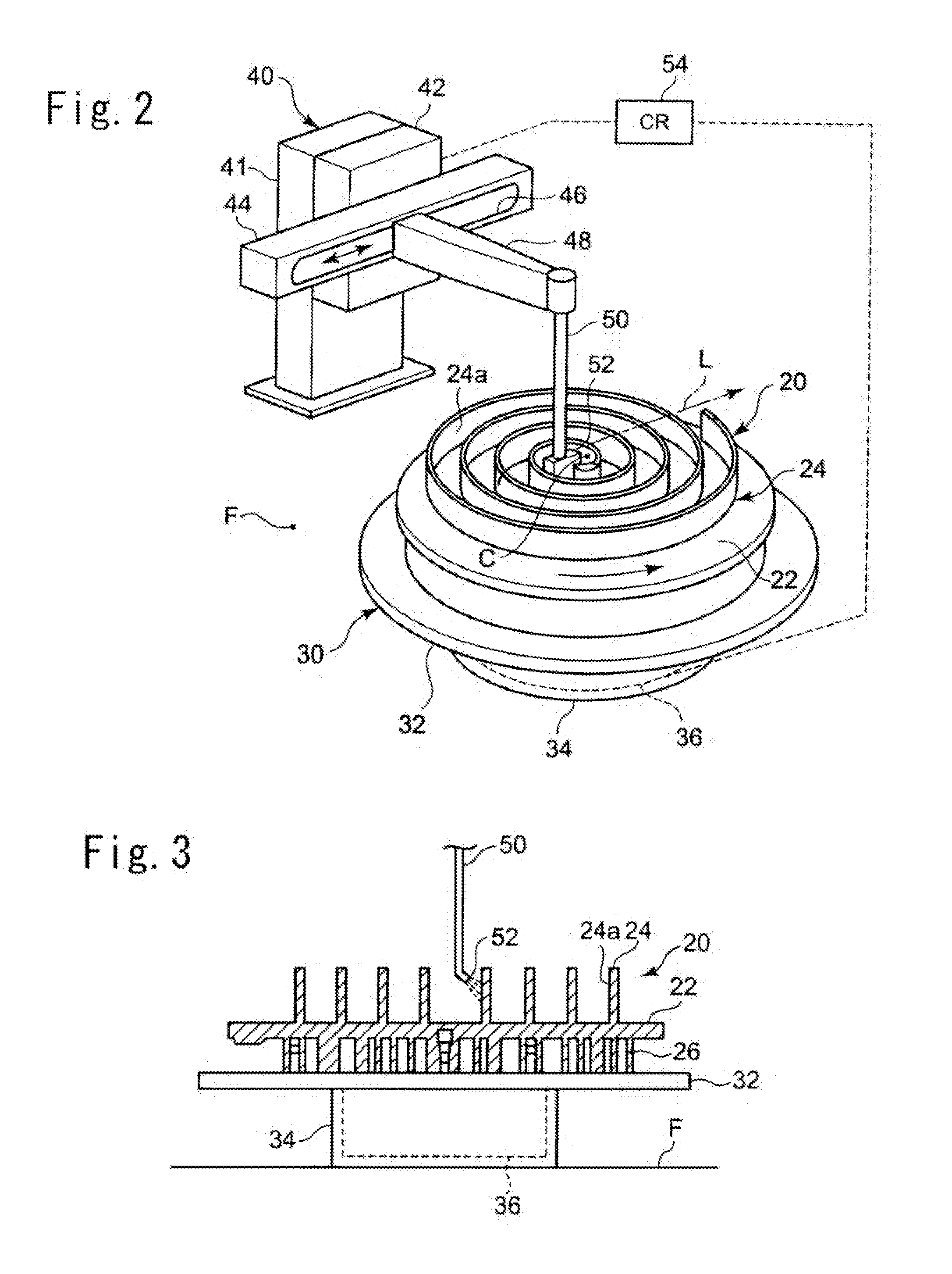
[0077]Next, a second embodiment of the coating method according to the present invention will be described using FIGS. 5 and 6. A discharge port 58 of a spray nozzle 56 takes the shape of an elongated slit extending in a vertical direction. A dimension h2 of a long side of the discharge port 58 is set to be substantially identical to a height dimension h1 of the wrap portion side face 24a. Hence, when the coating solution is discharged from the discharge port 58, the coating solution can be applied to the entire region of the wrap portion side face 24a in a height direction extending from a connecting portion connected to the end plate 22 to a tip end portion in a single application. All other configurations of the coating device are identical to the first embodiment.

[0078]In the first embodiment and the second embodiment, examples in which the elastic coating is formed on the wrap portion of the orbiting scroll were described, but the elastic coating may be forme...


PUM


Abstract

A coating solution that contains 10 to 20% by weight of epoxy resin serving as a thermosetting resin, 20 to 30% by weight of MoS2, and 5 to 10% by weight of graphite, with a remainder thereof constituted by an organic solvent, is sprayed onto a wrap portion side face of an orbiting scroll from a spray nozzle . While spraying the coating solution, the orbiting scroll is rotated on a rotating table and the spray nozzle is moved along a rectilinear movement path toward a radial direction outer side of the orbiting scroll while maintaining an attitude thereof from the start of the spraying process. After applying the coating solution, the coating solution is dried by baking, whereupon a break-in operation is performed. As a result, an elastic coating is formed at a coating thickness that enables elastic deformation in accordance with a clearance between the wrap portion side faces.

Description

RELATED APPLICATIONS[0001]The present application is a continuation of International Application Number PCT / JP2011 / 077753, filed Dec. 1, 2011, and claims priority from Japanese Application Number 2011-006386, filed Jan. 14, 2011. The above listed applications are hereby incorporated by reference in their entirety.TECHNICAL FIELD[0002]The present invention relates to a scroll type fluid machine, and a method and a device for forming an elastic coating thereon, with which an elastic coating can be formed on a side face of a spiral wrap forming the scroll type fluid machine while preventing seizure, galling, wear, and contact damage on the wrap portion side face.BACKGROUND ART[0003]A scroll type fluid machine is used as a scroll type compressor, a scroll type vacuum pump, a scroll type expander, a scroll type air blower, and the like. A scroll type fluid machine is constituted by a fixed scroll and an orbiting scroll having spiral wrap portions that stand upright on end plates thereof,...

Claims


Application Information

Patent Timeline
Patent Type & Authority Applications(United States)
IPC IPC(8): F01C1/02
CPCF01C1/0269F04C18/0269B05B12/02B05B13/0228F04C2230/91F04C2240/20F05C2251/02F05C2251/14F05C2253/20
Inventor ASAMI, JUNICHISATO, TORU
Owner ANEST IWATA CORP
Why Eureka
Try Eureka