Misfuelling prevention device for a filler neck of a fuel tank

Active Publication Date: 2014-04-24
VOLKSWAGEN AG
View PDF28 Cites 9 Cited by
  • Summary
  • Abstract
  • Description
  • Claims
  • Application Information

AI Technical Summary

Benefits of technology

The patent describes a misfuelling prevention device for a fuel tank. The device consists of a tubular element with an inflow and an outflow side, which is mounted in the filler neck of the fuel tank. A closure element is mounted on the outflow side and can be opened or closed to prevent misfuelling. The tubular element has one or more openings that allow fuel to flow from the inside of the tubular element to the outside of the tank, even when the closure element is closed. The misfuelling prevention device can be retrofitted in the filler neck and can be designed to have a lower flow rate than a fuel dispensing facility to ensure reliable shut-off of the facility. The technical effect is to prevent misfuelling of vehicles with incorrect fuel types and to provide a reliable and efficient means of fuel tank filling.

Problems solved by technology

If a fuel dispensing nozzle with an unsuitable diameter is used in conjunction with the misfuelling prevention device, the discharge pipe either does not fit into the tubular element or is not able to actuate the tubular actuating element in order to open the closure element on account of a diameter that is too small.
This intuitively communicates to the user that the fueling process is not proceeding properly.

Method used


Image

  • Misfuelling prevention device for a filler neck of a fuel tank
  • Misfuelling prevention device for a filler neck of a fuel tank
  • Misfuelling prevention device for a filler neck of a fuel tank

Examples


Embodiment Construction

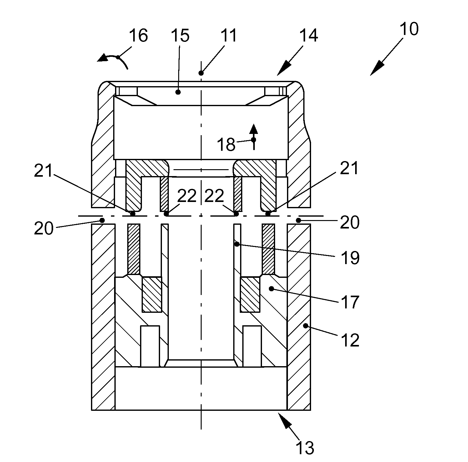
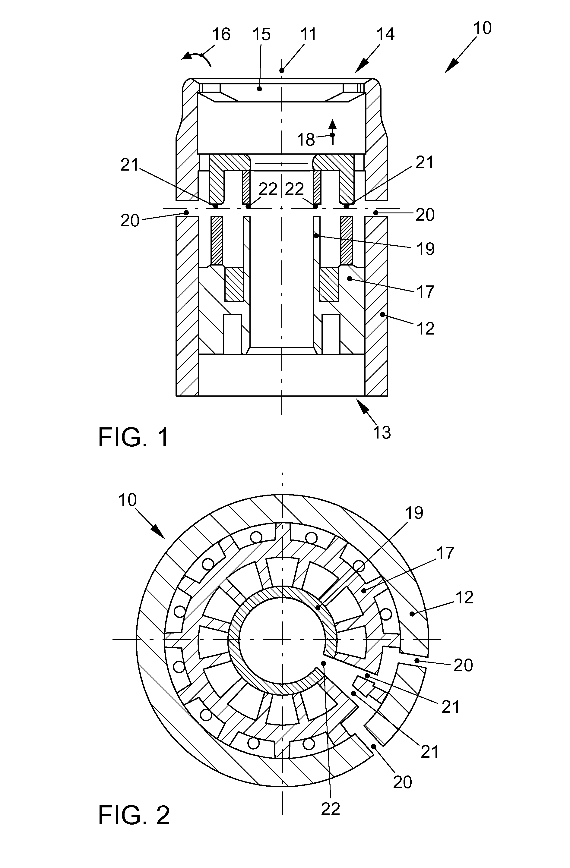
[0030]FIG. 1 shows a misfuelling prevention device 10 in a cross-sectional representation along a longitudinal axis 11. The misfuelling prevention device 10 comprises a tubular element 12 with an inflow side 13 and an outflow side 14. A closure element 15 is located on the outflow side 14. A discharge pipe of a gas pump nozzle is inserted into the tubular element 12 in the direction of the arrow 18 from the filling side 13. The closure element 15 can be, for example, a flap that obstructs flow of fuel through the outflow side 14 in a closed state and can be swung open about a hinge axis (not shown) in the direction of the arrow 16 in order to permit a flow of fuel through the outflow side 14. Arranged in the tubular element 12 is a tubular actuating element 17 that is movable in the direction of the longitudinal axis 11 within the tubular element 12. The tubular actuating element 17 can be moved in the direction of the arrow 18, for example when the discharge pipe of the gas pump no...


PUM

PropertyMeasurementUnit
Flow rateaaaaaaaaaa
Diameteraaaaaaaaaa

Abstract

A misfuelling prevention device for a filler neck of a fuel tank includes a tubular element with an inflow side and an outflow side and a closure element, which, when in an open state, permits a flow of fuel through the outflow side, and, when in a closed state, prevents a flow of fuel through the outflow side. In a shell surface of the tubular element there is formed at least one opening which permits a flow of fuel from an inner side of the tubular element through to an outer side of the tubular element. The tubular element can be mounted such that at least a part of the shell surface in which the at least one opening is formed is arranged spaced apart from an inner surface of the filler neck such that fuel flowing through the at least one opening can flow via the filler neck into the fuel tank.

Description

[0001]This nonprovisional application is a continuation of International Application No. PCT / EP2012 / 002571, which was filed on Jun. 19, 2012, and which claims priority to German Patent Application Nos. DE 10 2011 107 361.6 and DE 10 2011 120 787.6, which were filed in Germany on Jun. 29, 2011 and Dec. 9, 2011, respectively, and which are all herein incorporated by reference.BACKGROUND OF THE INVENTION[0002]1. Field of the Invention[0003]The present invention relates to a misfuelling prevention device for a filler neck of a fuel tank, and also concerns a filler neck with a misfuelling prevention device.[0004]2. Description of the Background Art[0005]Motor vehicles such as passenger cars or transportation vehicles may be operated with gasoline or diesel, depending on the type of internal combustion engine used. In the event of misfuelling, for example when a diesel vehicle is filled with gasoline, the vehicle can sustain substantial damage when it is operated. Moreover, substantial co...

Claims


Application Information

Patent Timeline
IPC IPC(8): B60K15/077
CPCB60K15/077B60K15/04B60K2015/0483B60K2015/0461
Inventor BREUER, THORSTENSCHARPING, CHRISTIAN
Owner VOLKSWAGEN AG
Why Eureka
Try Eureka