Antenna structures combining metamaterials

a technology of metamaterials and antennas, applied in the field of electromagnetism waves, can solve the problems of only working with linear polarized antennas and drawbacks, and achieve the effect of great simplicity of manufactur

Active Publication Date: 2014-04-24
ECOLE SUPERIEURE ELECTRONIQUE DE LOUEST
View PDF1 Cites 19 Cited by
  • Summary
  • Abstract
  • Description
  • Claims
  • Application Information

AI Technical Summary

Benefits of technology

[0031]Thus, a structure made of left-handed material based on S-shaped resonators has great simplicity of manufacture. However, it has the drawback of not working when the polarization of the antenna is circular.

Problems solved by technology

However, this left-handed material structure based on split-ring resonators and conductive strips has several drawbacks.
One of the drawbacks of this structure of left-handed material based on split-ring resonators and conductive strips is that it works only with linear polarization antennas.
However, it has the drawback of not working when the polarization of the antenna is circular.

Method used


Image

  • Antenna structures combining metamaterials
  • Antenna structures combining metamaterials
  • Antenna structures combining metamaterials

Examples


first embodiment

6.1 Radome Made of Metamaterials According to the Invention

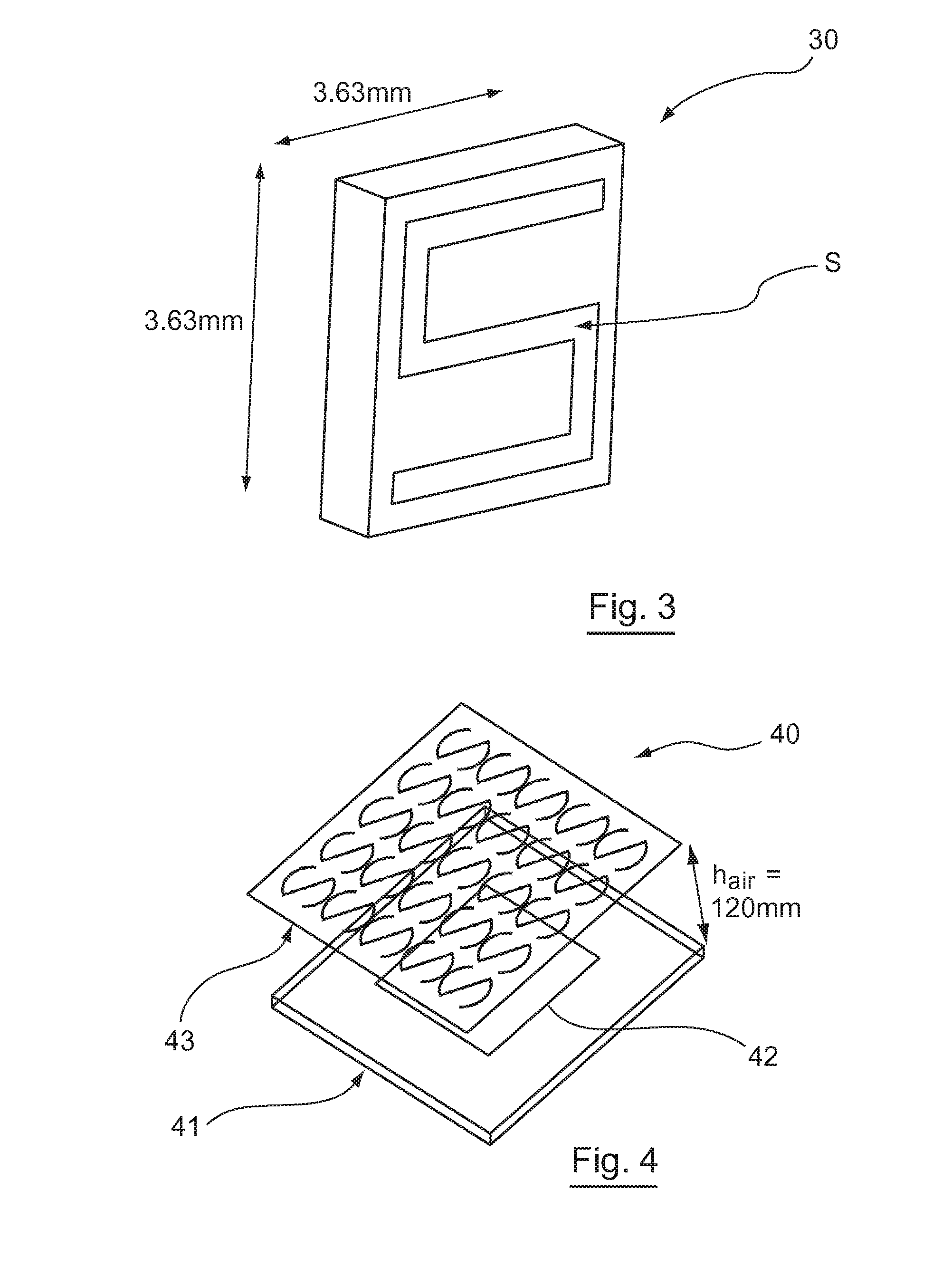
[0089]FIG. 4 illustrates an example of an antenna system comprising a radome made of metamaterial according to a first embodiment of the invention.

[0090]The antenna system 40 comprises:[0091]a patch antenna 401 comprising:[0092]a carrier structure (for example a dielectric, magnetic or air layer) 41;[0093]a square-shaped radiating element 42; and[0094]a radome 43.

[0095]The antenna system 41 is configured and sized to work in the UHF-RFID band. The UHF-RFID band extends from 860 MHz to 960 MHz.

[0096]FIG. 5 presents an example of an antenna 401 according to the invention. This FIG. 5 illustrates an example of an embodiment of the carrier structure 41 and the radiating element 42.

[0097]In the example of FIG. 5, the carrier structure 41 has a ground plane 51 printed on the lower face of a first layer 52 of dielectric material. The carrier structure 41 comprises a second layer 54 of dielectric material which is separated from the...

second embodiment

6.2 A Radome Made of Metamaterials According to the Invention

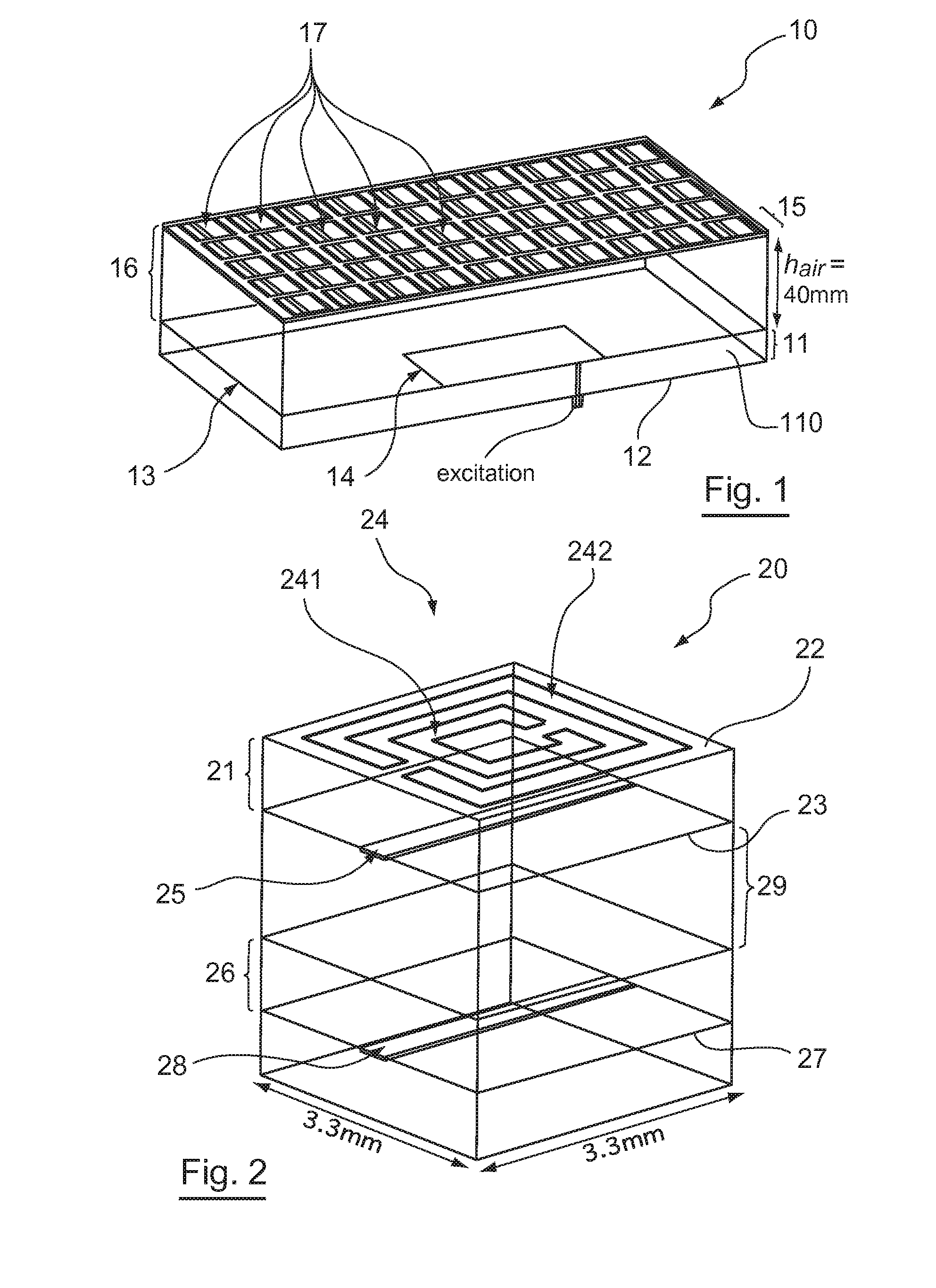
[0140]FIG. 12 illustrates an example of an antenna system comprising a radome made of metamaterials according to a second embodiment of the invention.

[0141]The antenna system 120 comprises:[0142]a patch antenna 125 comprising:[0143]a carrier structure 122;[0144]a square-shaped radiating element 123; and[0145]a radome 121.

[0146]The carrier structure 122 and the radiating element 123 are respectively identical to the carrier structure 41 and the radiating element 42 described here above with reference to FIGS. 4 and 5. These elements are therefore not described again here below.

[0147]The radome 121 comprises a metamaterial structure. This metamaterial structure comprises a plurality of elementary blocks according to the invention.

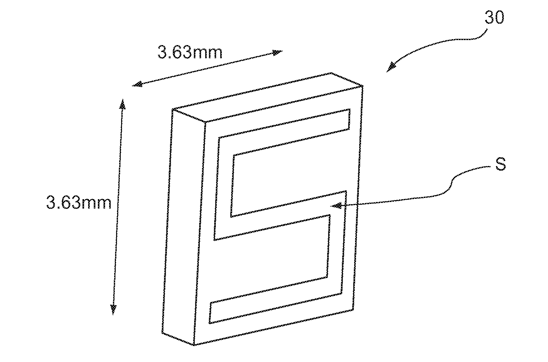
[0148]Referring now to FIG. 13, we describe an elementary block of metamaterial according to a second embodiment of the invention.

[0149]In this second embodiment of the invention, the elementary blo...


PUM


Abstract

A metamaterial structure including at least one basic unit including a mounting made of a dielectric material. The mounting has an upper surface and a lower surface. Each basic unit includes an electrically conductive unit arranged on the upper surface of the mounting and including: a first C-shaped conductive element including first and second ends; a second C-shaped conductive element including third and fourth ends, the first and second conductive elements being arranged relative to one another such that the first and third ends are opposite one another and separated by a first space, and the second and fourth ends are opposite one another and separated by a second space; and a connector configured so as to connect the first end to the fourth end.

Description

1. CROSS-REFERENCE TO RELATED APPLICATIONS[0001]This Application is a Section 371 National Stage Application of International Application No. PCT / EP2012 / 054841, filed Mar. 19, 2012, which is incorporated by reference in its entirety and published as WO 2012 / 130661 on Oct. 4, 2012, not in English.2. FIELD OF THE INVENTION[0002]The field of the invention is that of electromagnetic waves, preferably in the ultra-high frequency (UHF) range (300 MHz to 3 GHz) or the microwave frequency (3 GHz to 300 GHz) range.[0003]More specifically, the invention pertains to a structure of metamaterials comprising elementary blocks of metamaterial as well as an antenna system (here below also called an antenna structure) using such a structure of metamaterials as an antenna radome.[0004]The invention can be applied especially but not exclusively to all antenna systems for which it is sought to increase the directivity and the antenna gain and minimize the rear and lateral radiation. For example, the in...

Claims


Application Information

Patent Timeline
Patent Type & Authority Applications(United States)
IPC IPC(8): H01Q15/00
CPCH01Q15/0086H01Q15/0026
Inventor LATRACH, MOHAMEDABDOUNI-ABDALLAH, WAFA
Owner ECOLE SUPERIEURE ELECTRONIQUE DE LOUEST
Why Eureka
Try Eureka