
Combustor cap assembly

a technology of cap plate and combustor, which is applied in the field of combustor, can solve the problems of high thermal stress on the cap plate, and achieve the effect of reducing the thermal stress of the cap pla

Active Publication Date: 2014-05-01
GENERAL ELECTRIC CO
View PDF13 Cites 21 Cited by
  • Summary
  • Abstract
  • Description
  • Claims
  • Application Information

AI Technical Summary

Benefits of technology

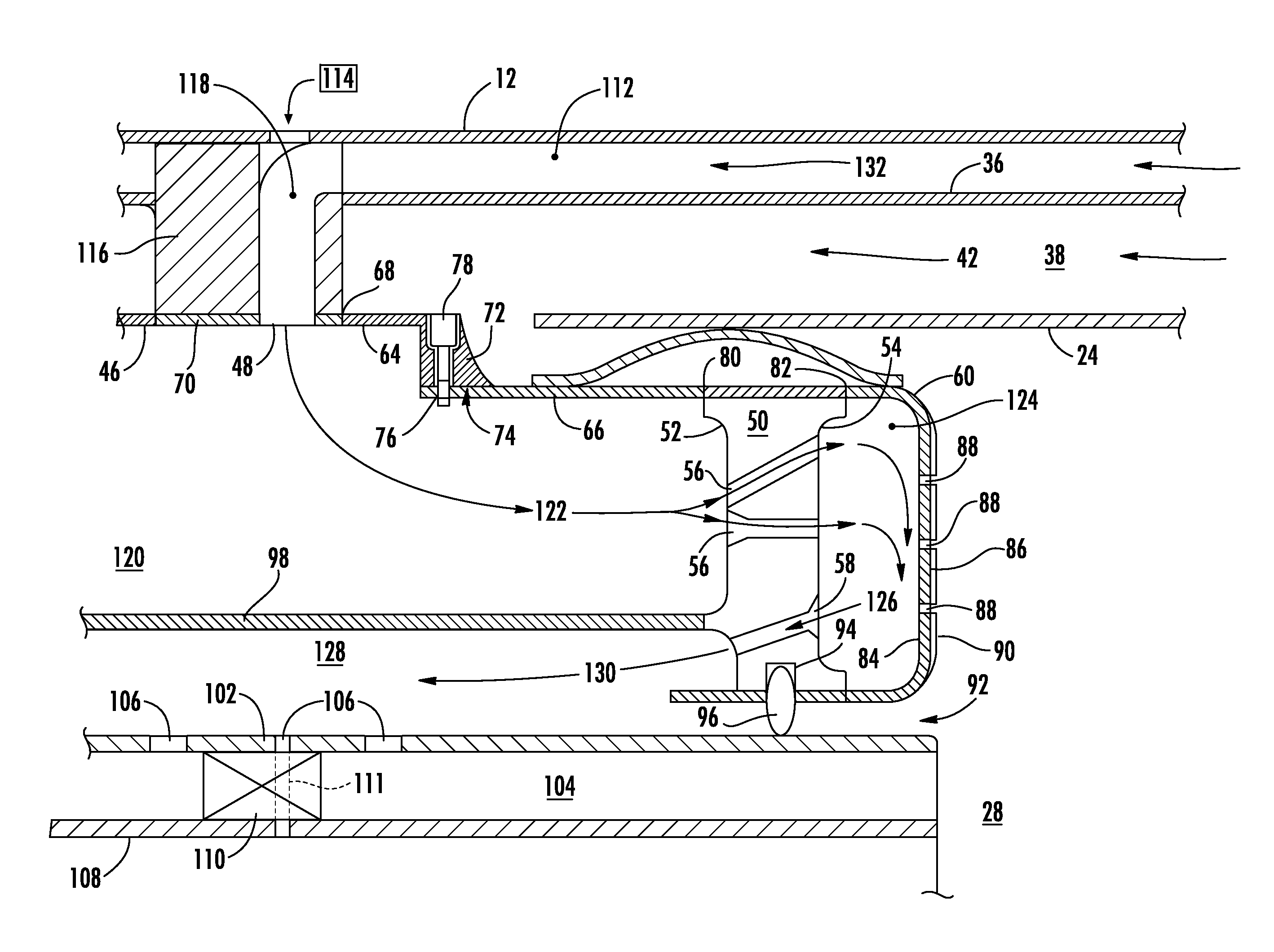
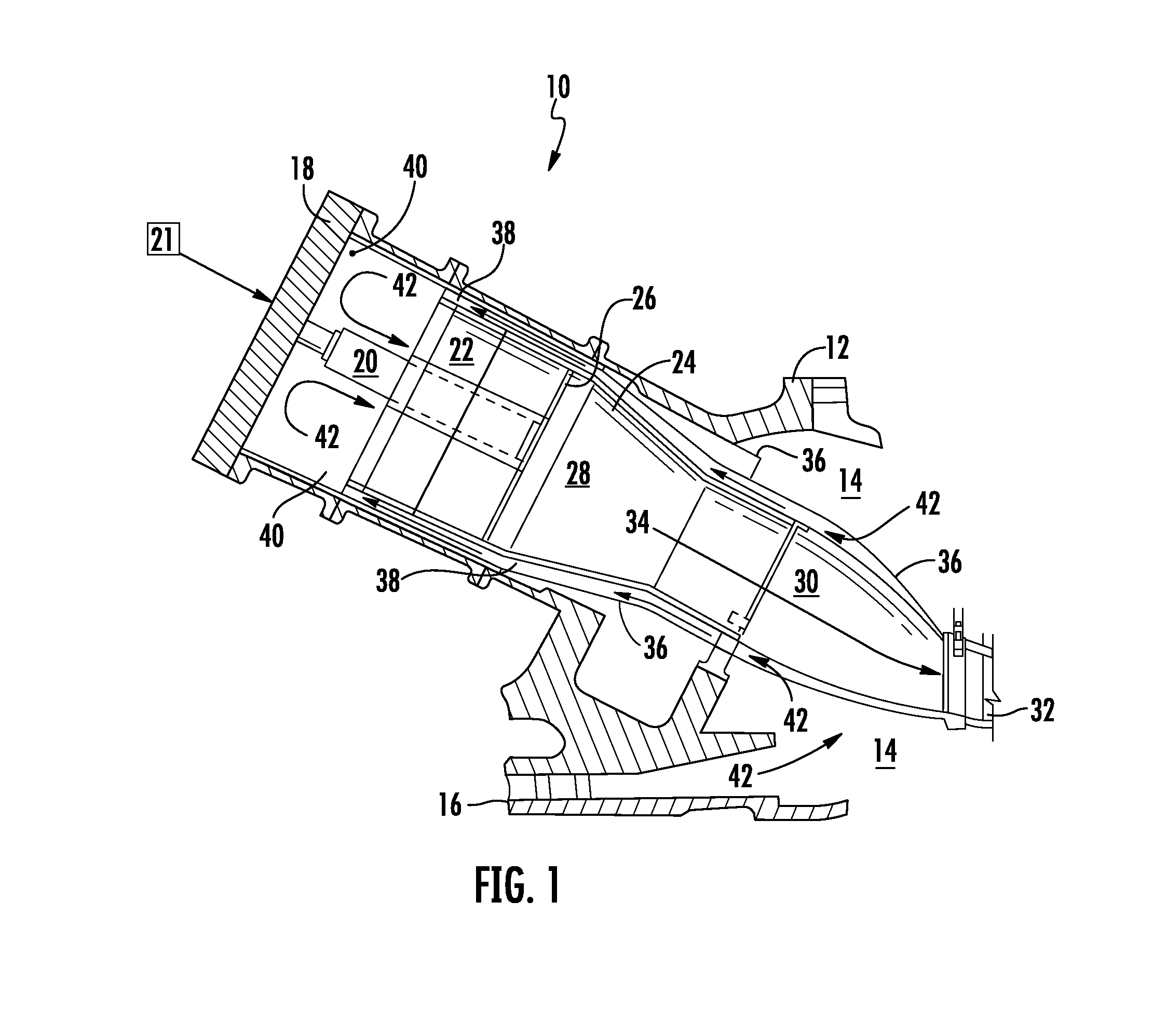
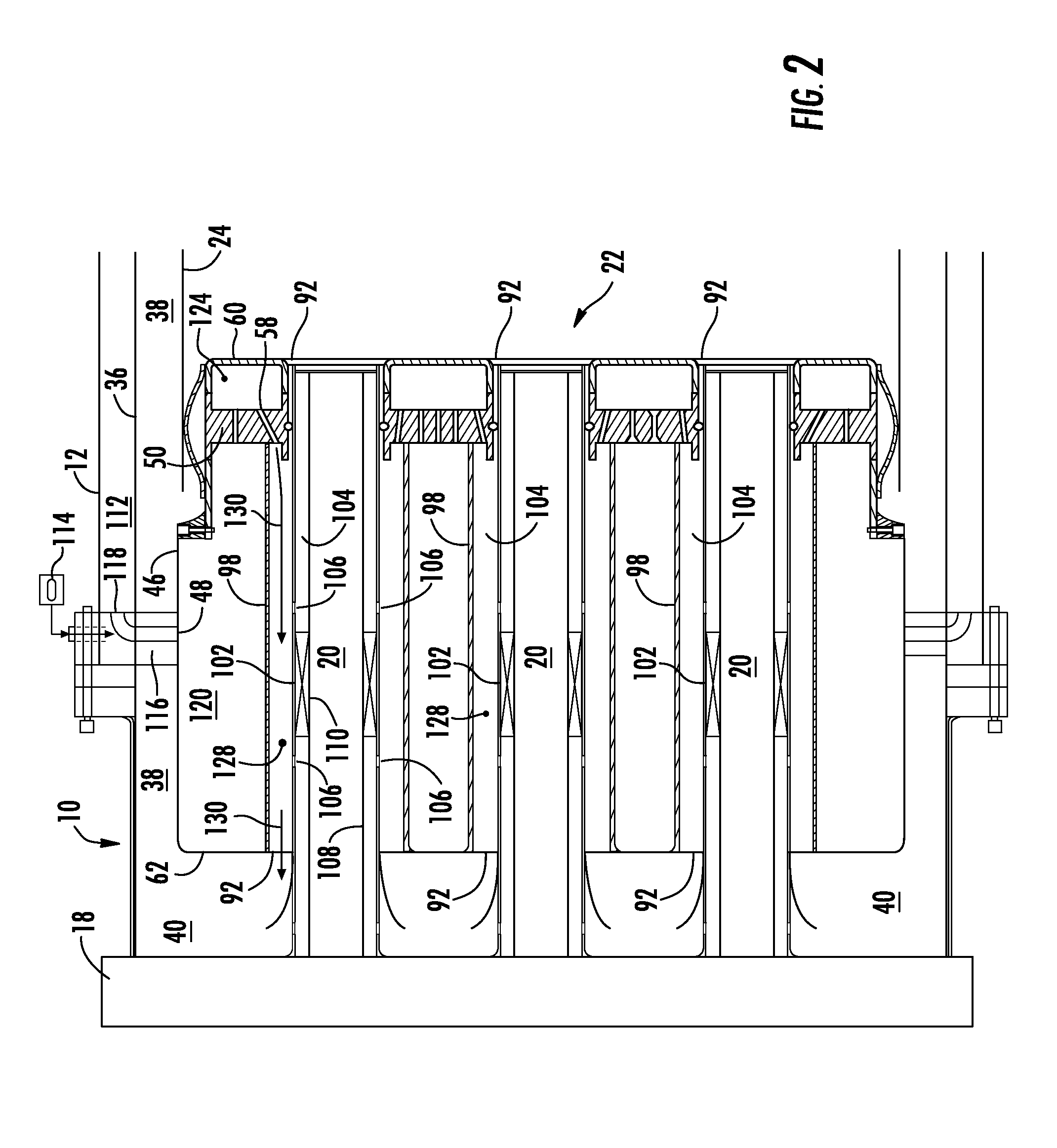
The patent describes a new design for a combustor, which is a part of a gas turbine engine. The design includes a shroud that extends inside the combustor and defines one or more inlet passages. The first plate extends radially inside the shroud and defines the inlet port, the outlet port, and a fuel nozzle passage. A second plate extends radially around the first plate and upstream from the outlet port. A sleeve is at least partially surrounded by the shroud and extends radially outward from the fuel nozzle passage. A tube is at least partially surrounded by the sleeve and extends through the fuel nozzle passage. The design also includes one or more fluid flow paths that allow the air and fuel to flow through the combustor. The technical effects of this design include improved air and fuel mixing, reduced emissions, and improved engine performance.

Problems solved by technology

As a result, the cap plate is generally exposed to extremely high temperatures, thus resulting in high thermal stresses on the cap plate.
However, the compressed working fluid flowing through the multiple cooling holes may enter the combustion zone generally unmixed with the fuel.

Method used


Image

  • Combustor cap assembly
  • Combustor cap assembly
  • Combustor cap assembly

Examples


Embodiment Construction

[0017]Reference will now be made in detail to present embodiments of the invention, one or more examples of which are illustrated in the accompanying drawings. The detailed description uses numerical and letter designations to refer to features in the drawings. Like or similar designations in the drawings and description have been used to refer to like or similar parts of the invention. As used herein, the terms “first”, “second”, and “third” may be used interchangeably to distinguish one component from another and are not intended to signify location or importance of the individual components. In addition, the terms “upstream” and “downstream” refer to the relative location of components in a fluid pathway. For example, component A is upstream from component B if a fluid flows from component A to component B. Conversely, component B is downstream from component A if component B receives a fluid flow from component A.

[0018]Each example is provided by way of explanation of the invent...


PUM


Abstract

A combustor generally includes a shroud that that defines at least one inlet passage extends circumferentially inside the combustor. A first plate extends radially inside the shroud downstream from the inlet passage. The first plate defines at least one inlet port, at least one outlet port and at least partially defines at least one fuel nozzle passage. The shroud at least partially surrounds a sleeve that extends around the fuel nozzle passage. A tube at least partially surrounded by the sleeve may extend through the fuel nozzle passage. The tube, the sleeve, and the first plate may at least partially define an outlet passage. A first fluid flow path generally extends from the at inlet passage to the inlet port, and a second fluid flow path extends generally from the outlet port to the outlet passage.

Description

FIELD OF THE INVENTION[0001]The present invention generally involves a combustor and method for cooling the combustor.BACKGROUND OF THE INVENTION[0002]Gas turbines often include a compressor, a number of combustors, and a turbine. Typically, the compressor and the turbine are aligned along a common axis, and the combustors are positioned between the compressor and the turbine in a circular array about the common axis. In operation, the compressor creates a compressed working fluid, such as compressed air, which is supplied to the combustors. A fuel is supplied to the combustor through one or more fuel nozzles and at least a portion of the compressed working fluid and the fuel are mixed to form a combustible fuel-air mixture. The fuel-air mixture is ignited in a combustion zone that is generally downstream from the fuel nozzles, thus creating a rapidly expanding hot gas. The hot gas flows from the combustor into the turbine. The hot gas imparts kinetic energy to multiple stages of ro...

Claims


Application Information

Patent Timeline
Patent Type & Authority Applications(United States)
IPC IPC(8): F02C7/18F23R3/26F23R3/54
CPCF23R3/283F23D11/36F23D14/78F23D2214/00F23R2900/03043F23R2900/03044F23R3/14F23R3/28F23R3/286
Inventor MELTON, PATRICK BENEDICTROMIG, BRYAN WESLEYSTOIA, LUCAS JOHN
Owner GENERAL ELECTRIC CO
Learn More