Flared Grip for Bicycle or Motorcycle Handlebar

a technology for handlebars and bicycles, applied in the field of bicycle or motorcycle handgrips, can solve the problems of limiting throttle control, affecting the grip, and affecting the grip, and achieve the effects of improving grip and control, increasing surface area, and ensuring safety

Inactive Publication Date: 2014-05-01
ROGERS DERRICK GARY
View PDF12 Cites 10 Cited by
  • Summary
  • Abstract
  • Description
  • Claims
  • Application Information

AI Technical Summary

Benefits of technology

[0010]A further object is to provide reference for the bicycle / motorcycle rider when grasping back onto the grip while keeping his / her eyes on the trail / road, and to keep the motorcycle rider from falling off, given the extreme lean angles achieved by modern day sportbikes.
[0011]A further object is to provide better grip and control for mountain bike type bicycle riders given the extreme riding conditions and large jumps which modern mountain bikes may negotiate.
[0012]These objects are achieved in a handgrip having the features specified above in that the present invention has a flared or bell shape. By making ½ of the body gradually thicker radially, particularly making this extra thickness with a flared or bell shape, the pressure placed upon the wrists is spread out because of the increased surface area of the flared shape, and extra sensitivity is transmitted to the palms of the riders' hands providing greater control and smoother throttle operation. The flared shape also allows the rider to apply more force to the bars while counter-steering allowing quicker steering inputs, and faster transitions from side to side as in an “S” turn or when negotiating a “chicane” on a racetrack, which relates directly to faster lap times on the racetrack and safer riding on the street. The flared shape allows for a more ergonomic grip for mountain bikers in which they can grip the bars more securely which relates to greater control during fast descents and greater sensitivity for superior control while jumping through the air.

Problems solved by technology

Because of this, a lot of weight and pressure is placed upon the hands and wrists while riding, which causes wrist strain and limits throttle control, which the conventional motorcycle grip of today does not address.
The conventional motorcycle grip does not address the issue of counter-steering.

Method used


Image

  • Flared Grip for Bicycle or Motorcycle Handlebar
  • Flared Grip for Bicycle or Motorcycle Handlebar
  • Flared Grip for Bicycle or Motorcycle Handlebar

Examples


Embodiment Construction

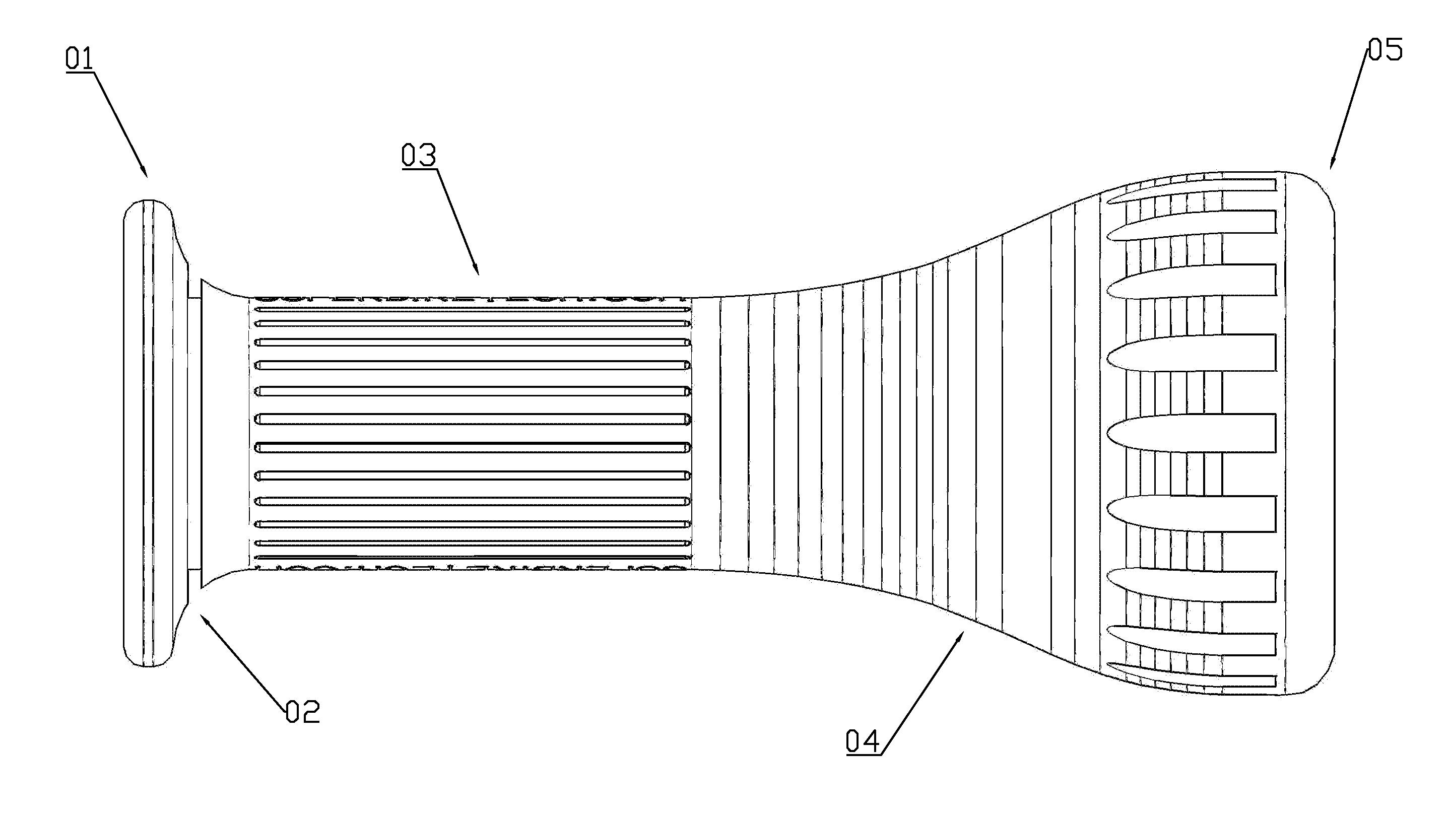
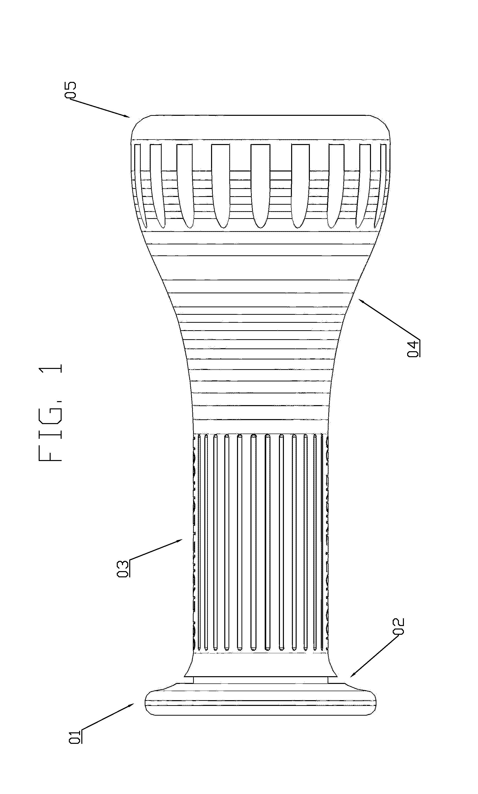
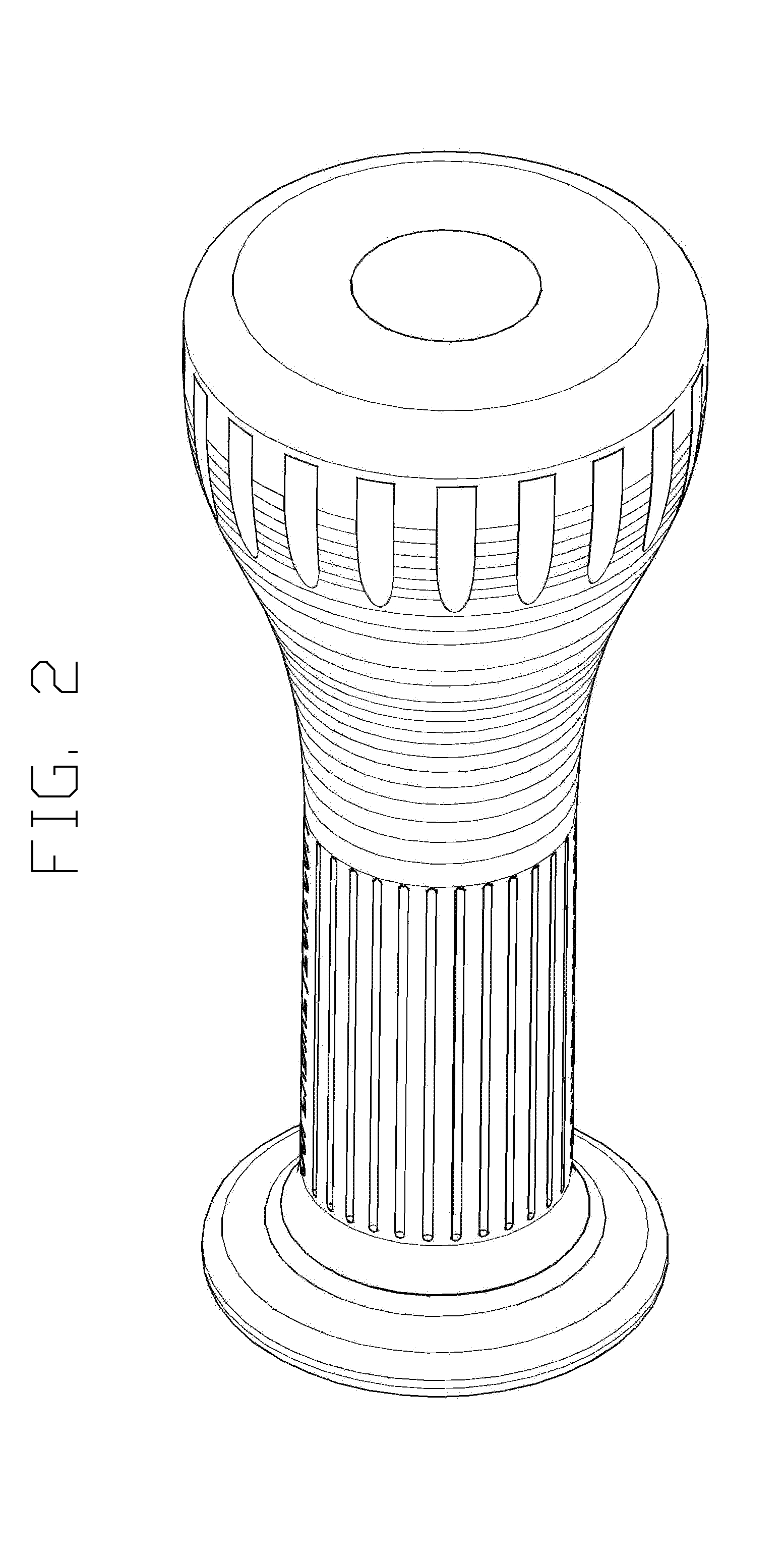
[0017]The hand grip illustrated in FIGS. 1 to 3 has a hollow cylindrical body with a first open end from which an annular flange 01 projects radially outwards, a safety wire groove 02 adjacent the annular flange, a constant external diameter approximately ½ the length of the body 03, a flared section 04 (comprising approximately the last ½ of the body), and a second end 05, which is flat and also open. The hand grip is formed from rubber (natural or synthetic).

[0018]The use of a gradual flare achieves these advantages without making the handgrip overall too thick for effective gripping / encircling by the rider's hand, as the end of the flared region 05 is over 10 mm less in diameter than a common tennis ball.

[0019]In other embodiments of the invention, which are not illustrated, the flare may have molded into it metal weights, which act as a vibration dampener.

[0020]Also, the external projections may be of a different shape and size to the illustrated embodiment.


PUM


Abstract

A flared or bell shaped motorcycle / bicycle handgrip which improves the design of handgrips, more specifically handgrips for mountain bike type bicycles and motorcycles with clip-on handlebars. Clip-ons are comprised of two separate short handles which are attached directly to the fork tubes, are placed lower than conventional handlebars, and are angled downward creating a lot of pressure on the wrists while riding. In order to alleviate wrist strain, and improve throttle control and steering inputs, the body of the present invention has an external surface which is flared. This flare spreads out the pressure and provides a larger surface for the palm to rest upon, and a larger surface area to grab onto, providing a more secure grip for mountain bikers. The flare is achieved by the base area progressively increasing in diameter, radially, the last half of the grip adjacent the second end, which is flat.

Description

CROSS REFERENCE TO RELATED APPLICATION[0001]This application claims the benefit of U.S. Provisional Application No. 61 / 795,887, filed Oct. 31, 2012, the contents of which are incorporated herein by reference.BACKGROUND OF THE INVENTION[0002]The present invention relates generally to bicycle or motorcycle handgrips and more specifically to a flared or bell shaped handgrip that offers features that are of benefit to riders of mountain bike type bicycles and supersport type motorcycles with clip-on style handlebars.[0003]The majority of conventional grips today are comprised of a hollow cylindrical body of flexible resilient material, such as rubber (natural or synthetic), having a first, open end, an opposing second end, which is also open, an annular flange projecting radially outwards at the first open end, and a constant diameter outer surface usually with a layer of projections or grooves to reduce slippage.[0004]Respective grips are fitted snugly (usually glued) onto each end of ...

Claims


Application Information

Patent Timeline
Patent Type & Authority Applications(United States)
IPC IPC(8): B62K21/26
CPCB62K21/26Y10T74/20828
Inventor ROGERS, DERRICK GARY
Owner ROGERS DERRICK GARY
Why Eureka
Try Eureka