Round Baler

a baler and round technology, applied in baling, agriculture tools and machines, agriculture, etc., can solve problems such as interference with baling operation, and achieve the effect of reducing crop production

Inactive Publication Date: 2014-05-01
CNH IND AMERICA LLC
View PDF8 Cites 8 Cited by
  • Summary
  • Abstract
  • Description
  • Claims
  • Application Information

AI Technical Summary

Benefits of technology

[0015]Because the end guide rolls are cantilever mounted on the belt tension arm assembly, there is no radius arm between the belt and the sidewall of the housing and there is only one small clearance required. In this way, it is possible to reduce the crop that can pass between the belts and the sidewalls.

Problems solved by technology

The wide gap results in crop finding its way behind the belts instead of being baled, and a build-up of crop can eventually interfere with the baling operation.

Method used


Image

  • Round Baler
  • Round Baler
  • Round Baler

Examples


Embodiment Construction

)

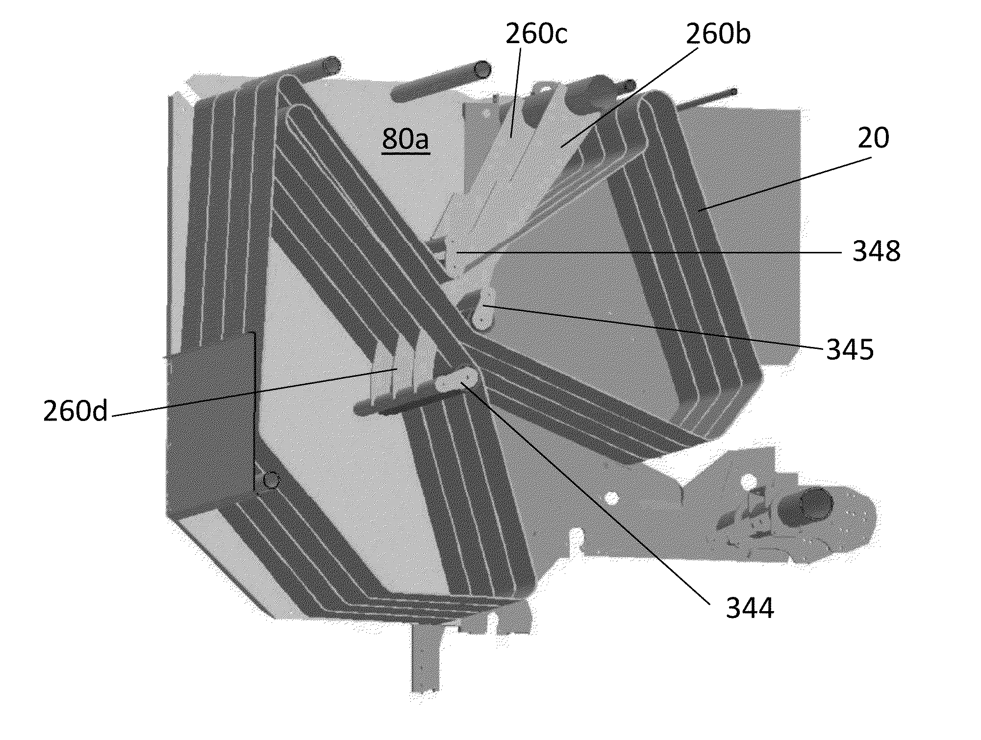
[0022]Referring now to FIG. 6, there is shown a modified design of belt tension arm assembly 260 to replace the assembly shown in FIGS. 1 to 5. To avoid repetition, like components have been allocated like reference numerals but in the 200 series. The important difference to note is that the radius arms 260b and 260c are no longer located adjacent the housing sidewalls 80 and they are not positioned at the axial ends of the axle 260a. Instead, they are spaced from the sidewalls 80 and from the ends of the axle 260a by a distance only slightly greater that the width of the end belt 20. The guide rolls 244, 245 and 248 for the end belts are cantilever mounted on the belt tension arm assembly 260 and extend laterally beyond the radius arms 260b and 260c.

[0023]In FIGS. 7 and 8, a third additional arm 260d is provided midway between the radius arms 260b and 260c. Note that the third arm 260d need not extend as far as the axle 260a. If more than four belts are used, such additional arms...


PUM


Abstract

A round baler is described having a housing with two sidewalls and a plurality of belts arranged side by side within the housing between the sidewalls and guided over rolls of which at least some are mounted movably to permit a baling to increase in diameter as the bale being formed grows in size. The movable rolls are supported by a belt tension arm assembly having radius arms extending from an axle that is rotatable relative to the housing about an axis parallel to that of the rolls. The rolls nearest the sidewalls of the housing are cantilevered mounted on the belt tension arm assembly to extend laterally beyond the radius arms.

Description

CROSS REFERENCE TO RELATED APPLICATIONS[0001]This Patent Application claims priority under 35 U.S.C. §119 to BE 2012 / 0743 filed on Oct. 30, 2012 titled, “Round Baler” and having Barbara De Craemer as an inventor. The full disclosure of BE 2012 / 0743 is hereby fully incorporated herein by reference.FIELD OF THE INVENTION[0002]The present invention relates to a round baler having a housing with two sidewalls and a plurality of belts arranged side by side within the housing between the sidewalls and guided over rolls of which at least some are mounted movably to permit a cylindrical volume bounded by sections of the belts to increase in diameter as the bale being formed grows in size.BACKGROUND OF THE INVENTION[0003]Round balers of the type described above are known and an example is to be found in EP 2269440. For convenience, FIGS. 1 and 2 of the latter patent are reproduced herein as FIGS. 1 and 2 of the accompanying drawings, in which:[0004]FIG. 1 is a side view of a round baler show...

Claims


Application Information

Patent Timeline
Patent Type & Authority Applications(United States)
IPC IPC(8): A01F15/07A01F15/18
CPCA01F15/07A01F15/18A01F15/0833A01F2015/186
Inventor DE CRAEMER, BARBARA
Owner CNH IND AMERICA LLC
Why Eureka
Try Eureka