Application of downhole rotary tractor

Active Publication Date: 2014-05-01
SAUDI ARABIAN OIL CO
View PDF7 Cites 3 Cited by
  • Summary
  • Abstract
  • Description
  • Claims
  • Application Information

AI Technical Summary

Benefits of technology

The patent describes a method for using a rotary tractor assembly to deploy drill strings, completion strings, production liners, casing, test strings, coil tubing, intelligent completion strings, and other downhole tools or systems into extended reach wells. The rotary tractor assembly provides a pulling force to reduce friction and prevent buckling of the pipe under high compression loading, which occurs when pushing from the surface alone. It also helps to introduce the string or tools into the very end of the wellbore, maximizing the exposure of strings, completion tools, and measuring devices to the well bore wall acting as the interface with the hydrocarbon-bearing formation. Overall, the method improves the efficiency and effectiveness of drilling and well construction.

Problems solved by technology

In horizontal drilling, there are many challenges to maintaining operations that are not present in vertical or even deviated systems.
The frictional force generated both while moving and when idle can damage the equipment.
Introducing these systems into a horizontal well having a long horizontal section, including extended reach wells (ERWs), multi-lateral and multi-tier wells and exposes operational difficulties.
These systems by themselves have difficulty reaching the technical objective (that is, the end of the well bore or Total Depth) due to the effect of gravity and friction.
Overcoming the friction of the horizontal section of the horizontal well bore is a significant, problem.
However, this is not recommended with intelligent systems because rotating the drill string can damage the external control and electrical lines and cause the completion to fail.
Since an intelligent completion string cannot be rotated, the exposure to friction increases with the length of the horizontal section.
Lubricants in the wellbore can reduce some effects of friction; however, their use can add complexity in terms of reservoir damage and cleanup.
Lubricants are costly and only marginally reduce friction (±10 to 20%).
Centralizers, however, have to be placed regularly along the length of the well bore and are prone to breaking and being pulled apart on the unlined well bore wall.

Method used


Image

  • Application of downhole rotary tractor
  • Application of downhole rotary tractor

Examples


Embodiment Construction

[0015]The Specification, which includes the Summary of Invention, Brief Description of the Drawings and the Detailed Description of the Preferred Embodiments, and the appended Claims refer to particular features (including process or method steps) of the invention. Those of skill in the art understand that the invention includes all possible combinations and uses of particular features described in the Specification. Those of skill in the art understand that the invention is not limited to or by the description of embodiments given in the Specification. The inventive subject matter is not restricted except only in the spirit of the Specification and appended Claims.

[0016]Those of skill in the art also understand that the terminology used for describing particular embodiments does not limit the scope or breadth of the invention. In interpreting the Specification and appended Claims, all terms should be interpreted in the broadest possible manner consistent with the context of each te...


PUM


Abstract

A towing string useful for positioning a towed assembly into a horizontal well bore includes a towed assembly coupled to a tractor assembly. The tractor assembly is operable to convert introduced energy into a pulling force that is directed downhole. The tractor assembly includes a disposable motor and a coupled rotary tractor. The rotary tractor has a rotating portion that is operable to rotate around a central axis of the rotary tractor and a rotary element that is operable to frictionally engage the well bore wall. A method for using the towing string for positioning the towed assembly in the horizontal section includes introducing the towing string into the horizontal well bore, operating the towing string such that the rotary element frictionally engages the well bore wall, and introducing energy to the towing string such that the tractor assembly provides a pulling force directed downhole.

Description

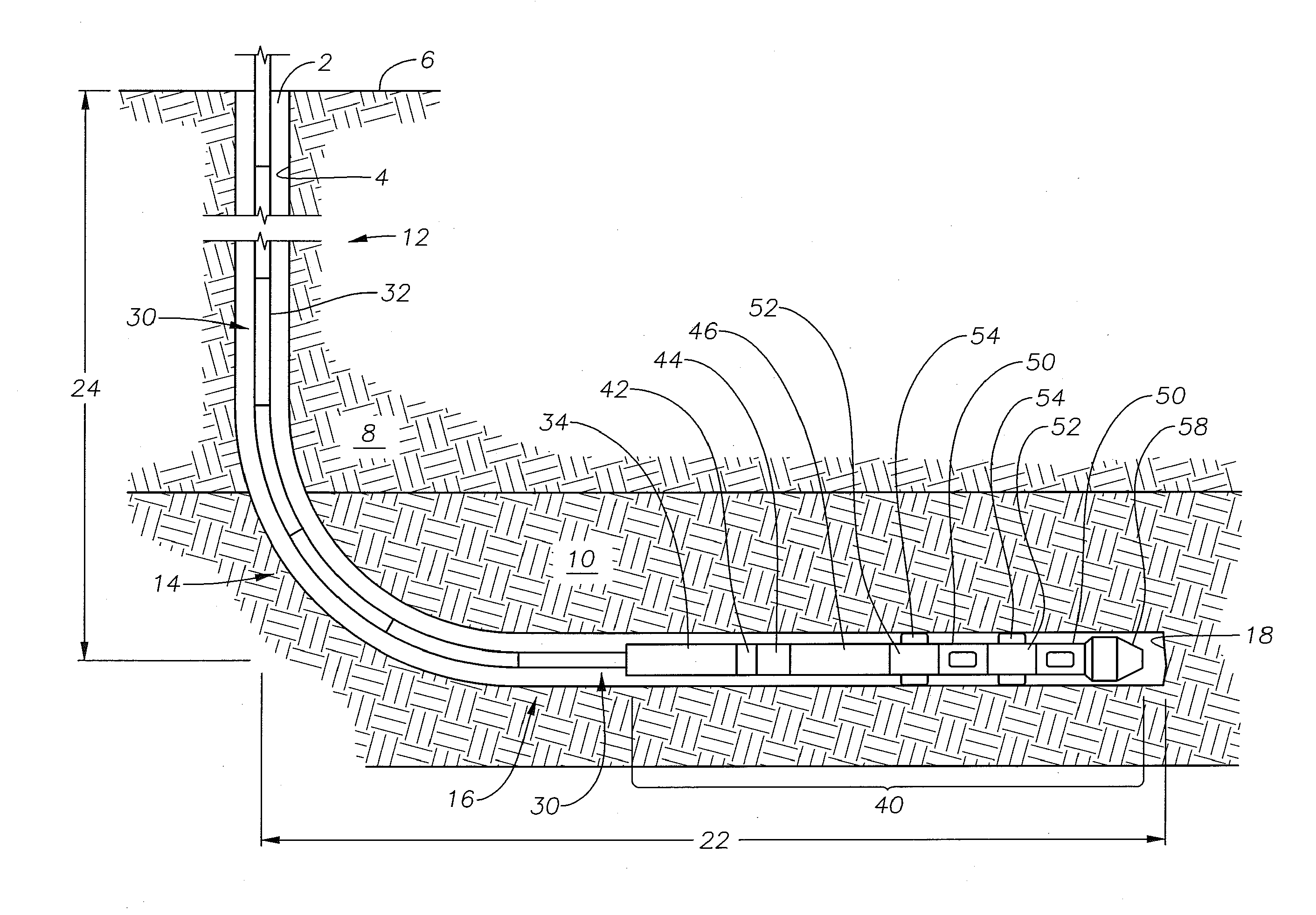
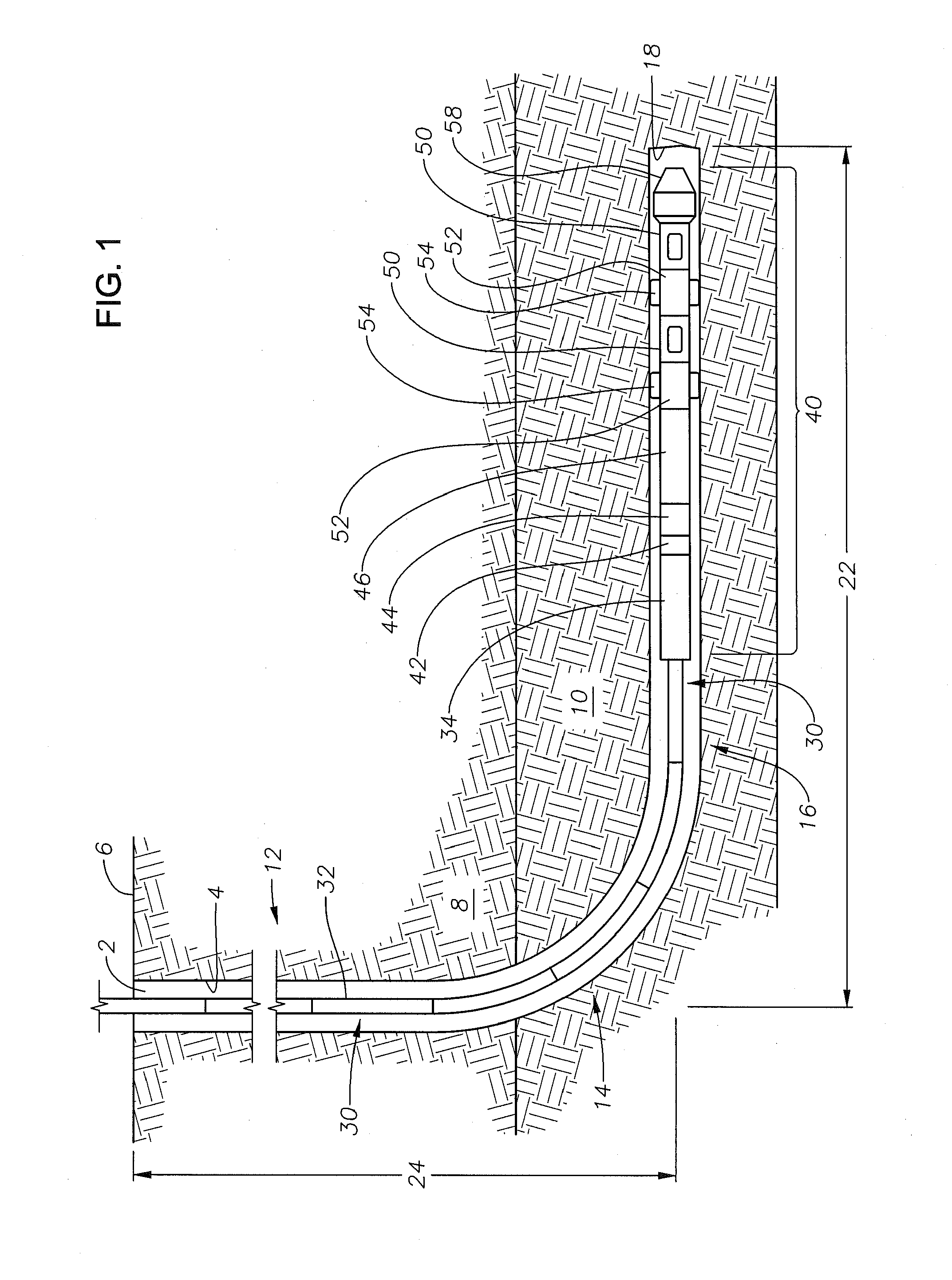
CROSS-REFERENCE TO RELATED PATENT APPLICATIONS[0001]This application claims priority from U.S. Provisional Application No. 61 / 718,926, filed Oct. 26, 2012. For purposes of United States patent practice, this application incorporates the contents of the Provisional Application by reference in its entirety.BACKGROUND OF THE INVENTION[0002]1. Field of the Invention[0003]The field of invention relates to a device and method for using a rotary tractor in a horizontal well bore.[0004]2. Description of the Related Art[0005]In horizontal drilling, there are many challenges to maintaining operations that are not present in vertical or even deviated systems. Gravity pulls the metal drill pipes, the drill collars, the drill bit and downhole tools against the walls of the well bore. The frictional force generated both while moving and when idle can damage the equipment. Much more energy is required to move a similar distance from the surface entry point horizontally than vertically. Today, exte...

Claims


Application Information

Patent Timeline
IPC IPC(8): E21B44/00E21B7/04
CPCE21B44/005E21B7/046E21B4/00E21B4/18E21B23/001
Inventor FRASER, SCOTT DAVID
Owner SAUDI ARABIAN OIL CO
Why Eureka
Try Eureka