

Injection molded element and production method
a technology of injection molding and elements, applied in the direction of yarn, electrical equipment, sports equipment, etc., can solve the problems of heat generation, non-functional insulation, and two metal electrical conductors getting too clos
- Summary
- Abstract
- Description
- Claims
- Application Information
AI Technical Summary
Benefits of technology
Problems solved by technology
Method used
Image

Examples
Embodiment Construction
[0010]a.) Technical Task
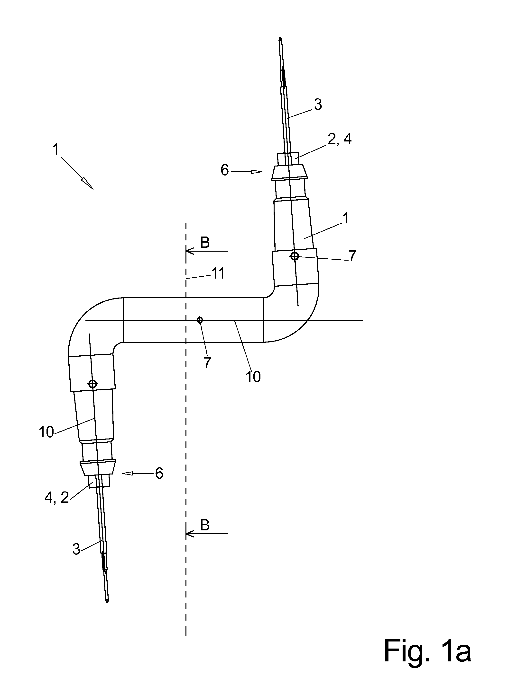
[0011]It is therefore the technical task of the invention to provide an injection molded element and a method for producing the element, wherein the element is producible in a simple and repeatable manner in spite of the conductors being run out without causing a risk of damaging the insulation of the electrical conductor and without a risk of plastic material exiting from the injection mold at the outlet location of the cable.
[0012]b.) Solution
[0013]The technical task is solved by the features of claims 1 and 18. Advantageous embodiments can be derived from the dependent claims.
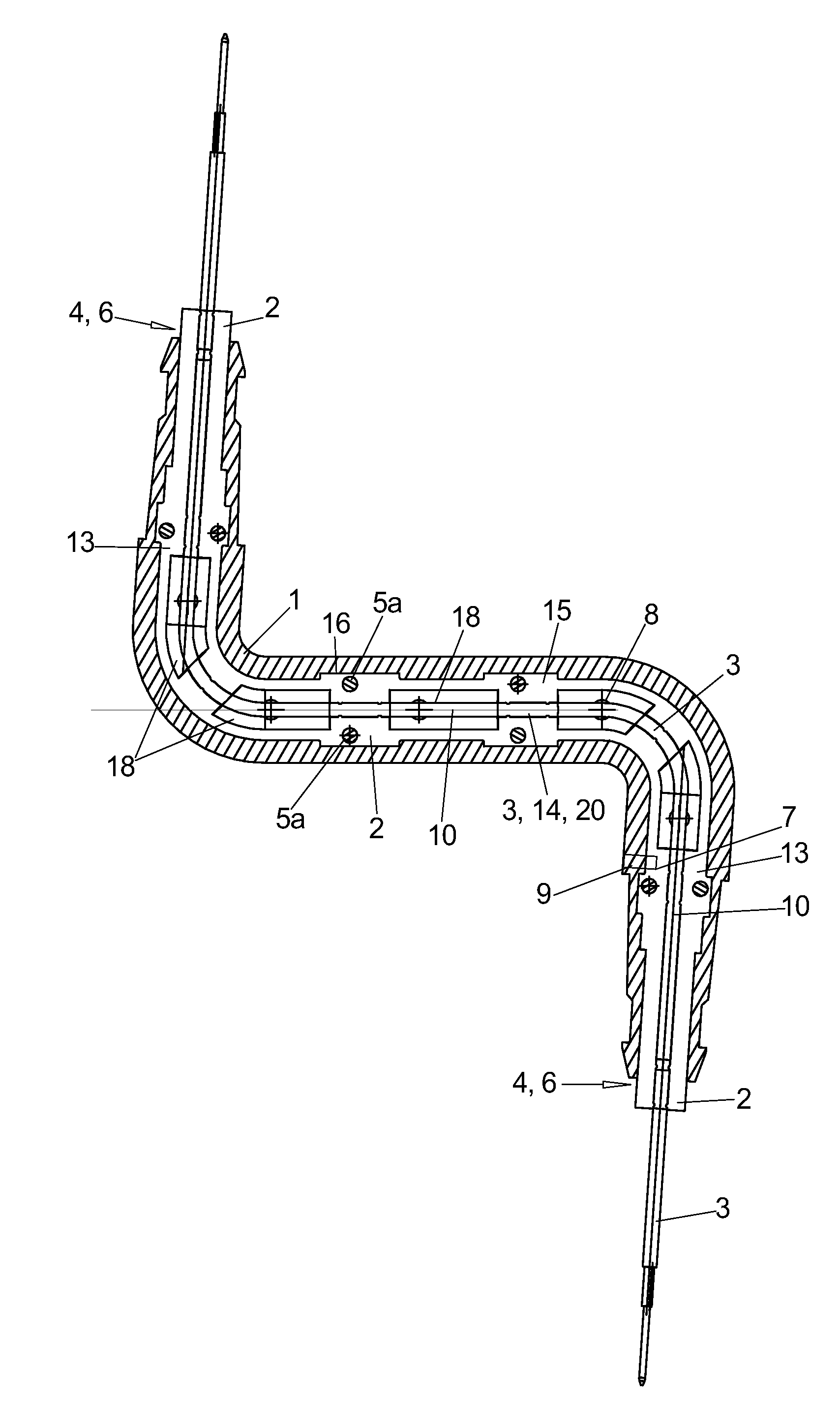
[0014]This object is achieved for the injection molded element according to the invention by molding the injection molded element onto an inner element and enveloping the cross section of the inner element advantageously from all sides, wherein the electrical conductor is inserted in the inner element.
[0015]This electrical conductor therefore is not encased by the inner element throug...
PUM
| Property | Measurement | Unit |
|---|---|---|
| distance | aaaaa | aaaaa |
| diameter | aaaaa | aaaaa |
| diameter | aaaaa | aaaaa |
Abstract
Description
Claims
Application Information