Vacuum lamination method for forming a conformally coated article and associated conformally coated articles formed therefrom

Active Publication Date: 2017-10-26
DOW SILICONES CORP
View PDF3 Cites 3 Cited by
  • Summary
  • Abstract
  • Description
  • Claims
  • Application Information

AI Technical Summary

Benefits of technology

The vacuum lamination methods described in this patent make it easy to create defect-free coatings on LED arrays. The method also allows for the use of preformed layers with different phosphor levels and binder compositions, which would be difficult in other methods. Additionally, the method can conformally coat LED arrays with variable heights.

Problems solved by technology

In this first heating step, the preformed laminated layer begins to cure (i.e., crosslink), therein reducing the flow characteristics of the layer, and hence the layer may be too stiff to be subsequently conformed during the second final heating step or, alternatively may be conformed but with substantial defects associated therewith.
Still further, even wherein the curing conditions during these two-step vacuum lamination techniques are precisely controlled, the processing time encompassing the second heating step and subsequent conforming of the preformed lamination layer over the array of LEDs is limited due to the partial curing of the binder material in the first heating step.
Also, the limited processing time during the second heating step and subsequent conformation step does not allow the two-step vacuum lamination technique to be used on arrays of LEDs of varying heights, and also limits the choices for binder materials and phosphor materials that may be used in two-step vacuum lamination techniques based upon this limited processing time.
Manufacturing other coated articles for a variety of applications such as other electronics applications, building, vehicle, healthcare, and consumer applications have many of the aforementioned lamination problems.

Method used


Image

  • Vacuum lamination method for forming a conformally coated article and associated conformally coated articles formed therefrom
  • Vacuum lamination method for forming a conformally coated article and associated conformally coated articles formed therefrom
  • Vacuum lamination method for forming a conformally coated article and associated conformally coated articles formed therefrom

Examples


first embodiment

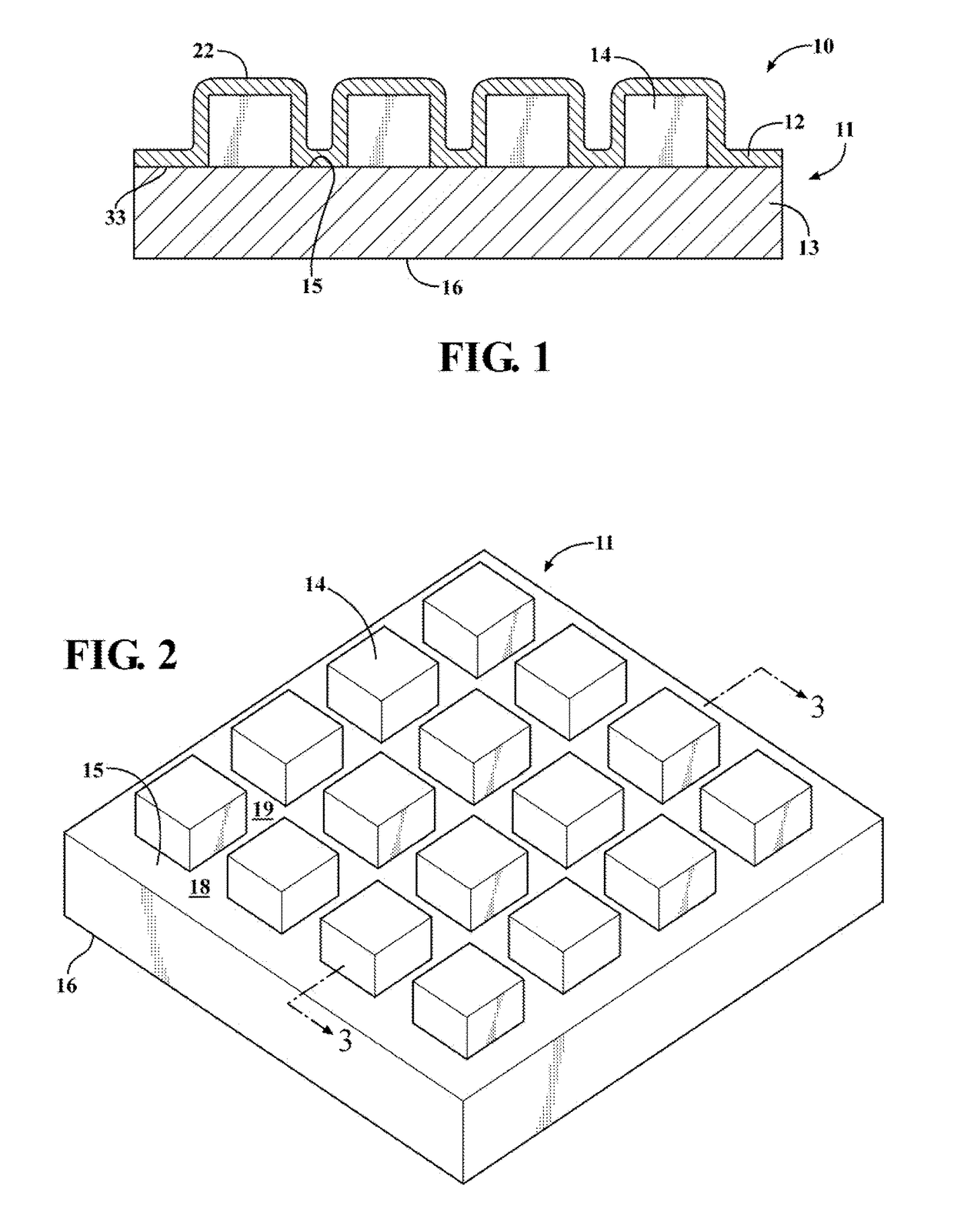
[0043]In the present invention, as illustrated in the logic flow diagram of FIG. 7, the method begins with Step 100, wherein the PL layer 12 is mounted over the LED array 11. The term “mounted”, as provided herein, refers to the placement of the PL layer 12 adjacent to the LED array 11, and is not intended to refer to or suggest that the PL layer 12 is fastened or otherwise secured to the array 11.

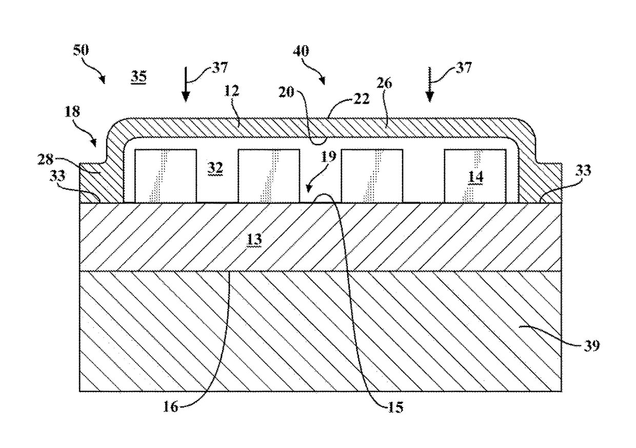
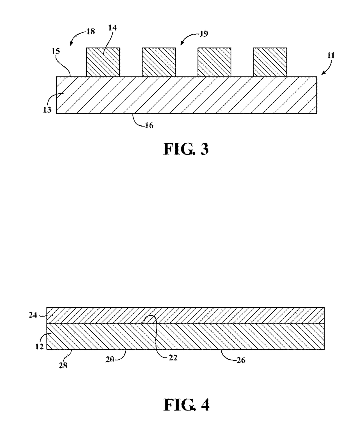
[0044]In certain embodiments, such as shown in FIGS. 5 and 6 prior to the PL layer 12 being conformally coated, the PL layer 12 is arranged wherein the first surface 20 of the PL layer 12 is located between the first side 15 of the submount wafer 13 and the second surface 22, and wherein the first side 15 of the submount wafer 13 is located between the first surface 20 and the second side 16. In this arrangement, the middle portion 26 of the PL layer 12 is adjacent to the inner portion 19 of the array 11, and therefore adjacent to the corresponding array of diodes 14, while the edge portio...

example 3

[0186] preparation of conformally coated LED array (3) using vacuum laminator (1): Replicate the procedure of Example 1d (140° C.) except use preformed lamination layer (3) instead of preformed lamination layer (1) to give conformally coated LED array (3). The lamination yield was 100%. Compare with Comparative Example 1 described above.

examples 4a

[0187] preparation of conformally coated LED array (4) using vacuum laminator (1): Replicate the procedure of Example 1d (140° C.) except use preformed lamination layer (4) instead of preformed lamination layer (1) and use a perimeter stamping jig configured to contact the entire edge portion of the second surface of the preformed lamination layer (4) and press same against the perimeter portion of the first side of the submount wafer while maintaining a gap between the edge portion of the first surface of the preformed lamination layer (4) and the perimeter portion of the first side of the submount wafer of LED array (1) so that the pressing does not tear the softened preformed lamination layer; use an initial heating time (after contact with hot plate but prior to vacuum release) of 15 seconds instead of 1 minute and 30 seconds; and use an additional heating time (after vacuum release) of 15 seconds instead of 2 minutes to give conformally coated LED array (4a). Total process time...


PUM

PropertyMeasurementUnit
Temperatureaaaaaaaaaa
Pressureaaaaaaaaaa
Perimeteraaaaaaaaaa

Abstract

Vacuum lamination methods for forming conformally coated articles having a preformed lamination layer conformally coated to or on an object such as an LED array are provided. These vacuum lamination methods utilize a single heating step to heat a middle portion of the preformed lamination layer to a flowable condition prior to the preformed lamination layer being conformally coated over the article, such as the array of light emitting diodes disposed on an inner portion of a first side of a submount wafer.

Description

FIELD OF THE INVENTION[0001]This invention generally provides a method for forming a conformally coated article, and the conformally coated article formed therefrom. More specifically, the method comprises a vacuum lamination method.BACKGROUND OF THE INVENTION[0002]A variety of coated articles can be fabricated by vacuum lamination for a variety of applications such as electronics, building, vehicle, healthcare, and consumer applications. For illustration, some electronics applications use coated electronic devices such as coated light emitting diodes. Light emitting diode (LED) devices including an array of light emitting diodes (LEDs) coupled to a substrate can be fabricated to generate light in different colors. One way for producing light of different colors or for otherwise controlling or manipulating the light generated from the LEDs is to deposit a phosphor material over the array of LEDs. There are many ways to do this. One of the most common ways is to dispense a mixture of...

Claims


Application Information

Patent Timeline
IPC IPC(8): H01L33/54H01L33/50B32B37/10H01L23/00
CPCH01L33/54H01L33/507H01L24/93B32B2457/00B32B37/1018H01L2933/0041H01L2933/005H01L33/502H01L25/0753H01L33/005H01L33/52H01L33/50H01L2924/0002B32B38/10B32B38/1866B32B37/003B32B2309/02B32B2309/04B32B2309/12B32B2457/14B32B2457/20H01L33/44H01L33/501H01L2933/0025B32B27/08B32B27/302B32B27/308B32B27/32B32B27/38B32B3/28B32B2307/40B32B2307/536B32B2307/71B32B2307/732B32B2419/00B32B2260/046B32B27/306B32B2605/00B32B2307/546B32B27/283B32B5/30B32B5/16B32B2264/10B32B2260/025
Inventor CUMMINGS, MICHELLE R.NISHIDA, FUMITOSHEPHARD, NICK E.
Owner DOW SILICONES CORP
Why Eureka
Try Eureka