Calibration jig for optical tomographic imaging apparatus and method for generating a calibration conversion table

a technology of optical tomographic imaging and calibration conversion table, which is applied in the direction of instruments, complex mathematical operations, measurement devices, etc., can solve the problems of the inability to evaluate the cost of the instrument, and the inability to correct the influence of the interferometer or the probe, etc., to achieve simple and repeatable manner

Active Publication Date: 2013-08-29
TERUMO KK
View PDF6 Cites 7 Cited by
  • Summary
  • Abstract
  • Description
  • Claims
  • Application Information

AI Technical Summary

Benefits of technology

The present invention provides a calibration jig for a probe optical tomographic imaging apparatus that can calibrate in a simple and repeatable manner. The calibration jig can correct distortion caused by dispersion at the optical probe's sheath. Additionally, the invention provides a method for generating a calibration conversion table that allows for easy and repeatable calibration of the optical tomographic imaging apparatus without needing to cut out a peak.

Problems solved by technology

This method, however, has drawbacks such that an expensive instrument is necessary for evaluation, it allows only correction for distortion of the frequency sweep characteristics of the light source, and influence of dispersion at the interferometer or the probe, for example, cannot be corrected for.
In this method, however, influence of the dispersion at the interferometer or probe, for example, cannot be corrected.
The above-mentioned Japanese Unexamined Patent Publication No. 2007-101365, however, does not disclose specific means in a case where the above-described calibration method is used.
In this method, however, wavelength distortion characteristics that are different from the characteristics in a case where an optical probe is used are introduced due to influence of optical components, such as a lens, of the measuring device, and this makes the calibration incomplete.
Further, ease and convenience are lost due to the size of the apparatus.
Further, since a protective member (sheath) for protecting the optical probe from a living body completely separate the optical axis scanning mechanism from the operator, it is very difficult to hold, fix and finely adjust the optical axis.
Therefore, when the optical probe covered with the sheath, which is used in actual measurement, is attached to the attachment section, to which the optical probe is optically coupled in a removable manner, of the optical tomographic imaging apparatus and a some type of reflective member is placed in the vicinity of the distal end of the optical probe to apply the measurement light to the reflective member, it is difficult for the operator to make the reflected light being reflected from the reflective member enter the optical probe with accuracy, and thus the calibration may not be repeatable.
In addition, since optical probes used in actual measurement have manufacturing variations, it is more difficult to achieve repeatable calibration if different optical probes are used in calibration operations carried out at different times.
When the measurement light and the reflected light transmit through the sheath, the measurement light and the reflected light are dispersed due to the wavelength dependency of refraction index, and this distorts the interference signal.
In general, criteria for selecting a cut-out region A for cutting out the peak largely vary depending on the technique used and conditions, and it is difficult to cut out the peak in a uniform manner.
Therefore, this method is time consuming and does not provide high accuracy.

Method used


Image

  • Calibration jig for optical tomographic imaging apparatus and method for generating a calibration conversion table
  • Calibration jig for optical tomographic imaging apparatus and method for generating a calibration conversion table
  • Calibration jig for optical tomographic imaging apparatus and method for generating a calibration conversion table

Examples


Embodiment Construction

[0062]Hereinafter, a calibration jig for an optical tomographic imaging apparatus according to the present invention will be described in detail with reference to the drawings.

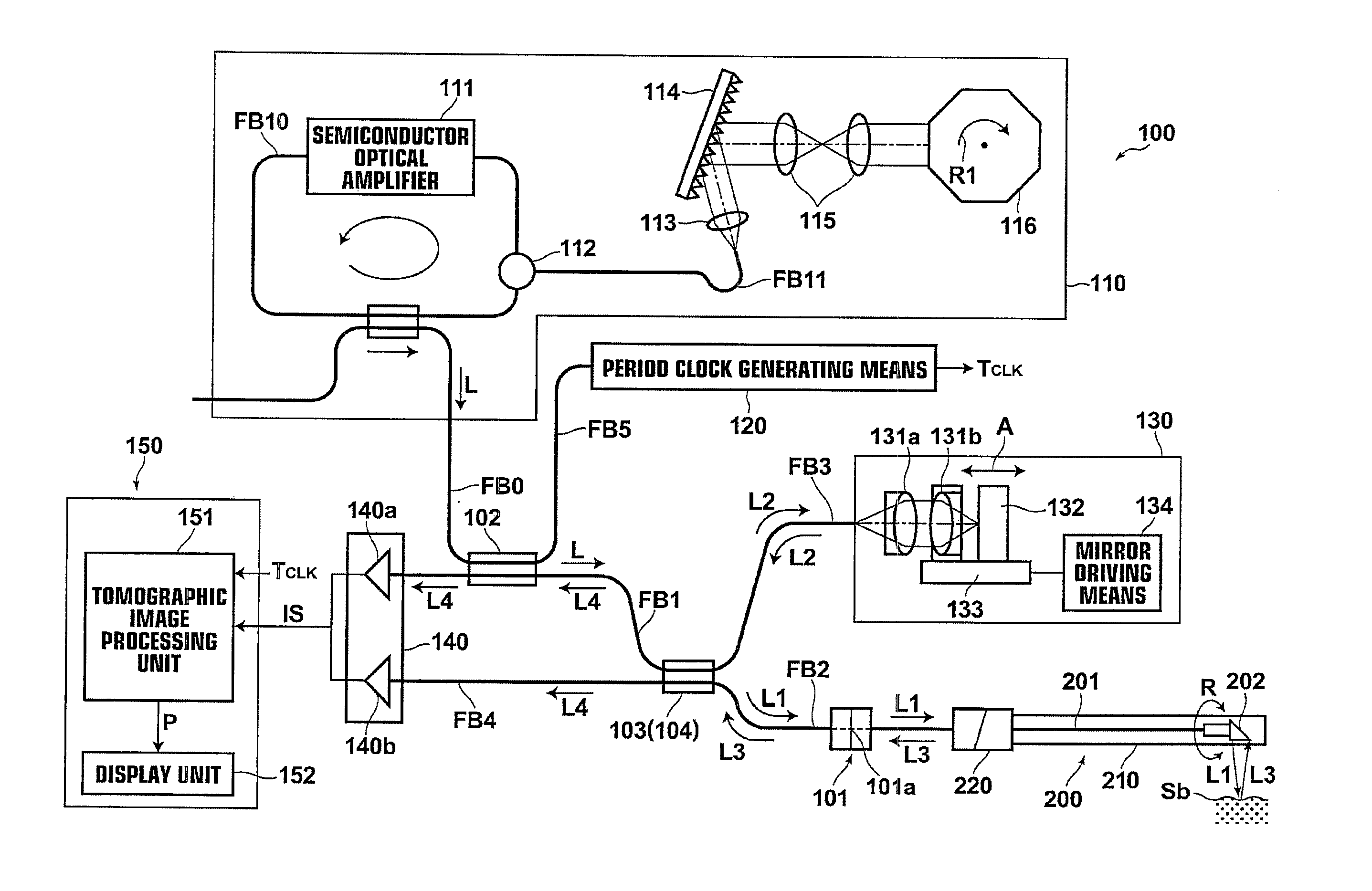
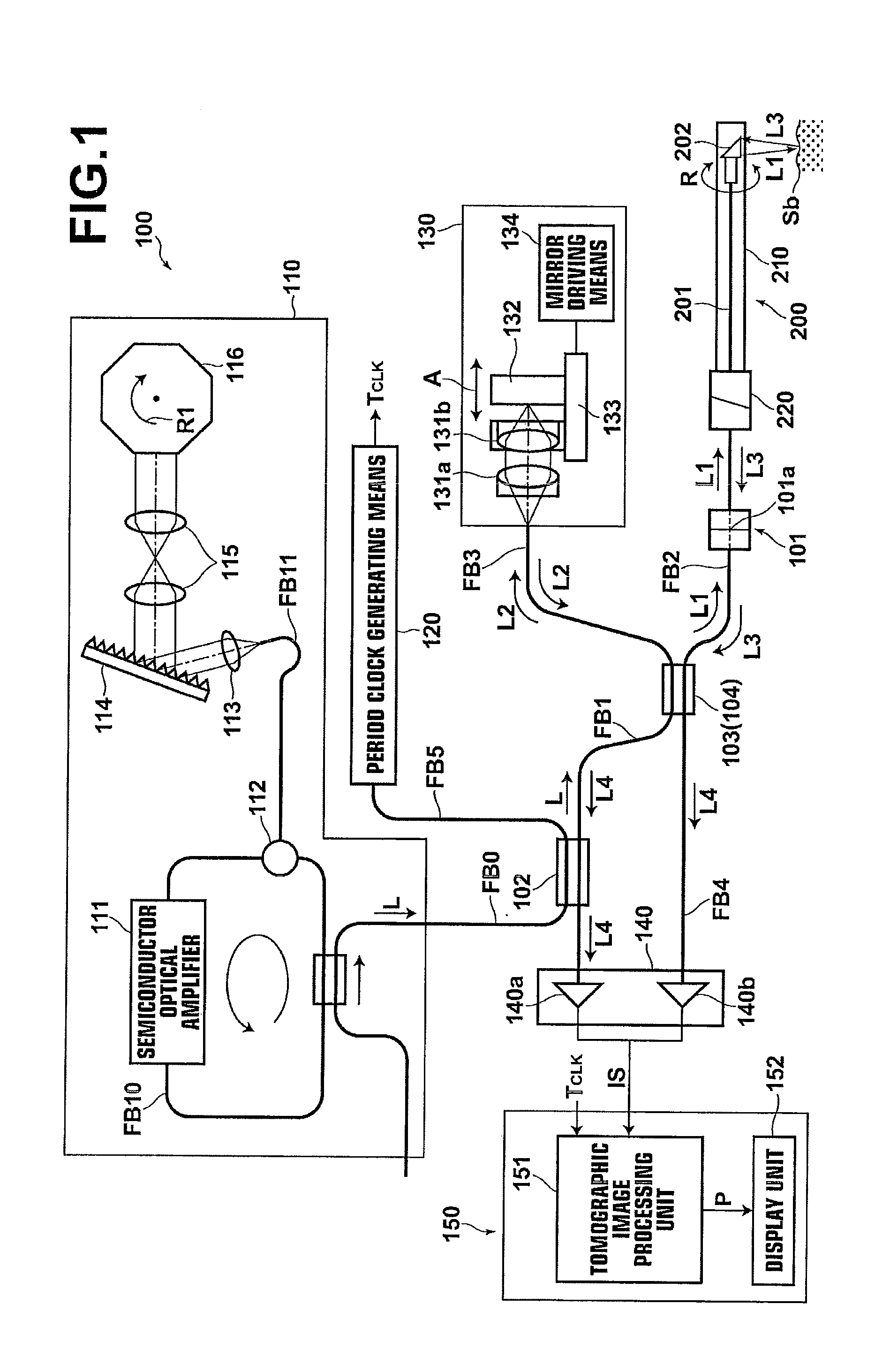
[0063]First, an optical tomographic imaging apparatus, which is calibrated using the calibration jig of the invention, and an optical probe are described. FIG. 1 illustrates the schematic configuration of the optical tomographic imaging apparatus and the optical probe. As one example, the optical tomographic imaging apparatus 100 acquires a tomographic image of a subject to be measured through SS-OCT measurement.

[0064]The optical tomographic imaging apparatus 100 includes: a light source unit 110, which emits laser light L; an optical fiber coupler 102, which divides the laser light L emitted from the light source unit 110; a period clock generating means 120, which outputs a period clock signal TCLK from the light divided by the optical fiber coupler 102; a light dividing means 103, which divides one of the l...


PUM


Abstract

A calibration jig allowing simple and repeatable calibration of a probe optical tomographic apparatus is disclosed. The jig includes a holding member removably attachable to an attachment section of the apparatus and a reflective surface held by the holding member. The reflective surface reflects measurement light emitted from an emitting section of the attachment section and directs reflected light back to the emitting section. If a probe of the apparatus is covered with a sheath, the jig may include a light transmitting member, which generates the same dispersion as dispersion at the sheath, between the emitting section and the reflective surface. The reflective surface may be a single reflective surface disposed within an area corresponding to twice a coherence length of the laser light with a zero path position of the reflective surface being the center of the area.

Description

[0001]This application is a Divisional of co-pending application Ser. No. 12 / 496,273 filed on Jul. 1, 2009, and for which priority is claimed under 35 U.S.C. §120; and this application claims priority under 35 U.S.C. §119 of Application No. 2008-172964 filed in Japan on Jul. 2, 2008, Application No. 2008-172965 filed in Japan on Jul. 2, 2008, and Application No. 2008-172966 filed in Japan on Jul. 2, 2008; and the entire contents of all these applications are hereby incorporated by reference.BACKGROUND OF THE INVENTION[0002]1. Field of the Invention[0003]The present invention relates to a calibration jig for an optical tomographic imaging apparatus and a method for generating a calibration conversion table. The present invention particularly relates to a calibration jig which is used for calibrating a probe optical tomographic imaging apparatus with the calibration jig being attached to an attachment section for receiving an optical probe of the optical tomographic imaging apparatus,...

Claims


Application Information

Patent Timeline
Patent Type & Authority Applications(United States)
IPC IPC(8): G01B9/02
CPCG01D18/00G01B9/02004G01B9/0205G06F17/17G01B9/02074G01B9/02072G01B9/02083G01B9/02091
Inventor WATANABE, DAISUKETERAMURA, YUICHI
Owner TERUMO KK
Why Eureka
Try Eureka