
Ventilator mask with a filler and method of production

a technology of ventilator mask and filler, which is applied in the field of ventilator mask, can solve the problems of adjusting the size of the mask, affecting so as to improve the comfort of wearing the mask, reduce the number of individual parts, and reduce the effect of patient discomfor

Active Publication Date: 2014-05-08
LOWENSTEIN MEDICAL TECH SA
View PDF10 Cites 0 Cited by
  • Summary
  • Abstract
  • Description
  • Claims
  • Application Information

AI Technical Summary

Benefits of technology

This design enhances wearing comfort, improves adaptability to diverse facial shapes, reduces the need for multiple mask sizes, and simplifies production by allowing for a one-part mask design with optimized compressive forces and sealing characteristics.

Problems solved by technology

The patient must wear the ventilator mask on his face for hours, overnight, or even for a period of several days, which means that great demands are placed on wearing comfort.
Complaints due to pressure points on parts of the face, especially the bridge of the nose, are a burden on the patient.
In addition, there is the problem of adjusting the size of the masks to different facial and nasal characteristics of different patients.
This makes it more difficult to adapt the upper part of the mask to the shape of the parts of the patient's face and makes it necessary to produce parts that are individually shaped for the patient.
This makes production more complicated and thus more expensive.

Method used


Image

  • Ventilator mask with a filler and method of production
  • Ventilator mask with a filler and method of production
  • Ventilator mask with a filler and method of production

Examples


Embodiment Construction

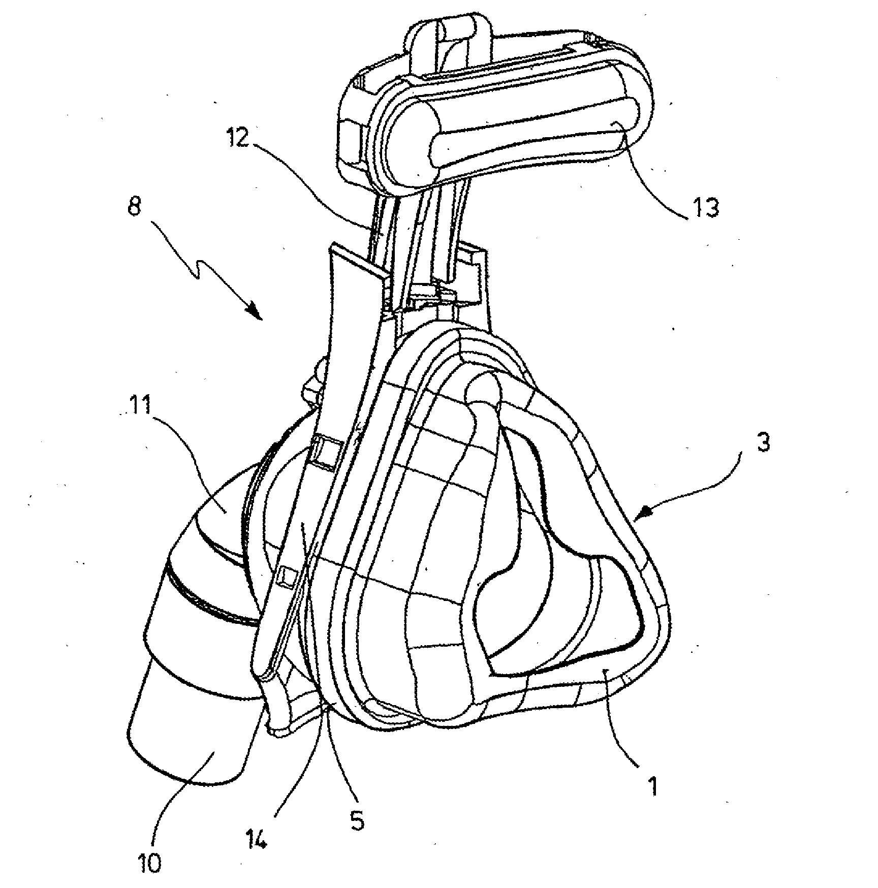
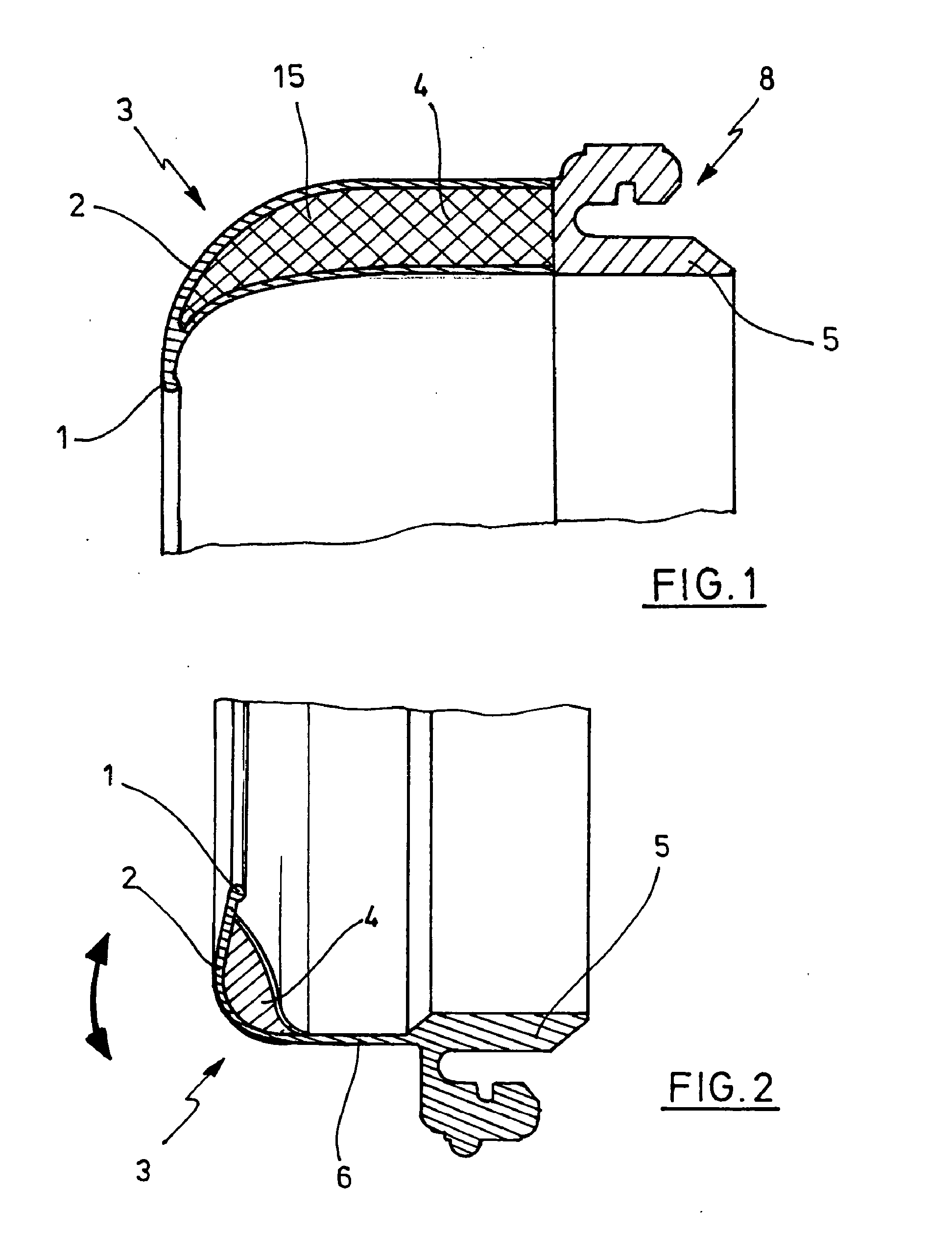
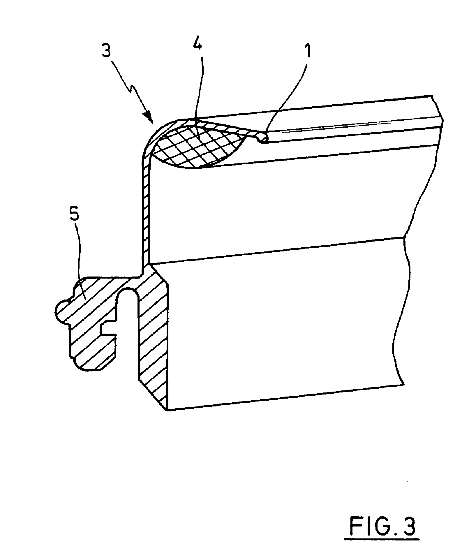
[0035]FIG. 1 shows a partial section of the upper part 3 of a ventilator mask 8, in whose walls a cavity 4 that is filled with a filler 15 is formed in such a way that the thickness or depth of the filler 15 varies over the cross section of the upper part 3 of the mask. The region of the upper part 3 of the mask that is in contact with the patient is preferably softer.

[0036]On its surface intended for contact with different parts of the patient's face, the upper part 3 of the mask terminates in a contact lip 1 that becomes thinner and surrounds the edge to provide the upper part 3 of the mask with a soft and flexible contact zone. The walls of the upper part 3 of the mask terminate in a mask connecting member 5, which is realized either as a single piece with the upper part 3 of the mask and made of the same material or as a separate part that is to be attached by adhesive bonding or welding.

[0037]The mask connecting member 5 is mechanically joined with a lower part of the mask (not...


PUM


Abstract

Disclosed is ventilator mask comprising an upper part of an elastic material and a mask body, wherein the upper part of the mask is joined with the mask body of the ventilator mask by a mask connection region, wherein a wall of the upper part of the mask bounds at least in certain regions of the wall a cavity which is filled with a filler at least in certain regions of the cavity and the cavity is formed at least in certain regions of the cavity along the periphery of the upper part of the mask.

Description

CROSS-REFERENCE TO RELATED APPLICATIONS[0001]The present application is a continuation of application Ser. No. 11 / 999,737, filed Dec. 6, 2007, the entire disclosure of which is expressly incorporated by reference herein.BACKGROUND OF THE INVENTION[0002]1. Field of the Invention[0003]The present invention relates to a ventilator mask.[0004]2. Discussion of Background Information[0005]In medical air supply, patients with a wide variety of respiratory problems are supplied by ventilation systems with air or with oxygen by means of devices that supply the air or an air mixture as a respiratory gas to the nose and / or the mouth. In this regard, the contact interface between the hoses supplying an air mixture and the respiratory openings of the person or other organism (since animals may also sometimes be supplied with respiratory gas) plays an important role.[0006]This interface is usually realized as a ventilator mask that covers only the nose, only the mouth, or both the nose and the mo...

Claims


Application Information

Patent Timeline
Patent Type & Authority Applications(United States)
IPC IPC(8): A61M16/06
CPCA61M16/06A61M16/0605A61M16/0616A61M16/0633A61M16/0825
Inventor EIFLER, MARTIN
Owner LOWENSTEIN MEDICAL TECH SA
Learn More