Graphene screening and separation method and device

a graphene and separation method technology, applied in the direction of fluid pressure measurement, liquid/fluent solid measurement, peptide, etc., can solve the problems of inability to display contrast, inability to achieve raman spectra, and inability to distinguish between two layers and a few layers of graphene sheets

Active Publication Date: 2014-05-08
METAL INDS RES & DEV CENT
View PDF1 Cites 4 Cited by
  • Summary
  • Abstract
  • Description
  • Claims
  • Application Information

AI Technical Summary

Benefits of technology

[0016]The present invention is to provide a graphene screening and separation method, which can determine the number of graphene layers by measuring a tunneling current.
[0018]The screening and separation method of the present invention can determine the number of graphene layers by measuring the tunneling current after using array electrodes with energy barrier layers formed by metal oxides to adsorb graphene with a dielectrophoretic force. The dielectrophoretic force can be continuously applied according to a particular number of graphene layers, or the dielectrophoretic force can be stopped, so that the particular number of graphene layers can be retained on the pair of electrodes, or the particular number of graphene layers can be released from the pair of electrodes, so as to finish the screening and separation method.

Problems solved by technology

The disadvantage is that the identification of the number of graphene layers with Quantum Hall effects needs to be carried out in a high magnetic field environment and thus is impractical and inefficient.
The disadvantage is that differences between two layers and a few layers of graphene sheets are not obvious in Raman spectra.
The disadvantage is that the contrast can be displayed only for a particular thickness and a substrate made of a particular material, which is difficult to be combined with the existing separation system.
The disadvantage is that batch separation of different layers of graphene has a bottleneck in purity upgrade, and currently the single-layer graphene may reach about 85% by this method.

Method used


Image

  • Graphene screening and separation method and device
  • Graphene screening and separation method and device
  • Graphene screening and separation method and device

Examples


Embodiment Construction

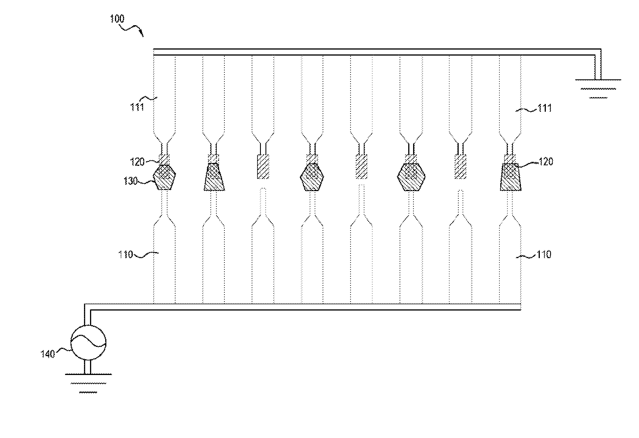
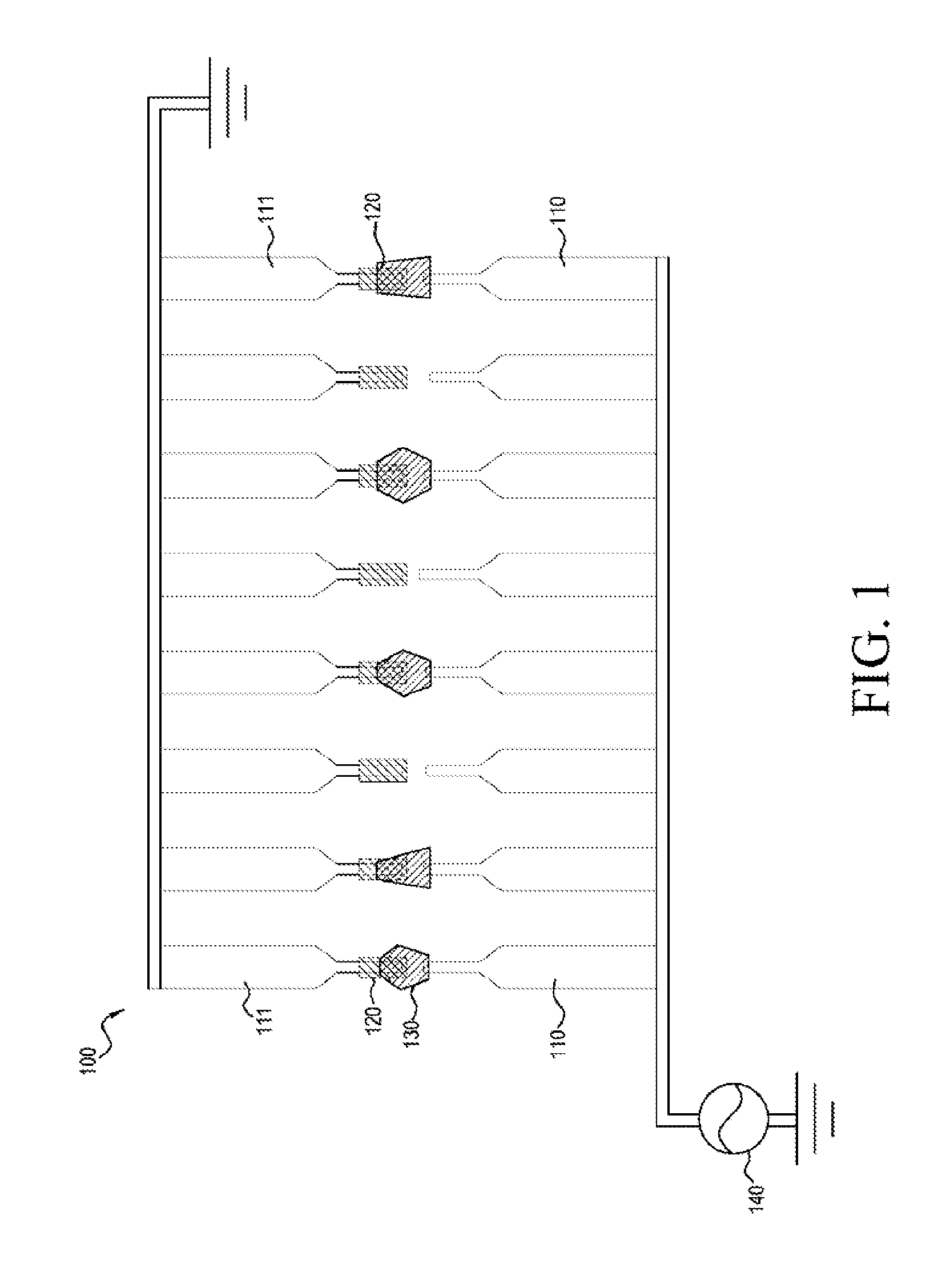
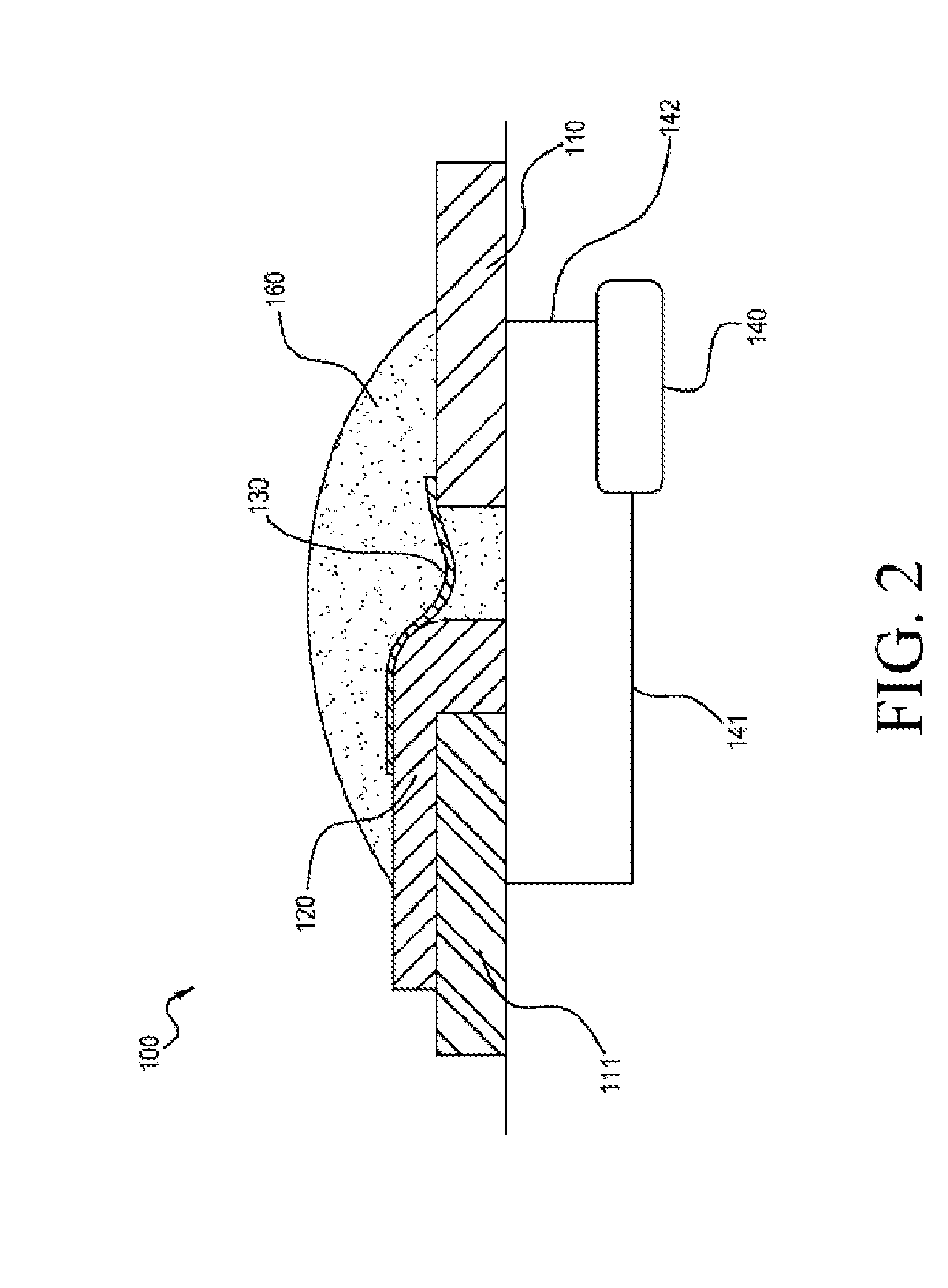
[0026]FIG. 1 and FIG. 2 show a graphene screening and separation device 100 illustrating an embodiment of the present invention. The graphene screening and separation device 100 includes at least one pair of electrodes, for example, multiple pairs of electrodes are arranged in an array, which is referred to as array electrodes. Each pair of electrodes consists of first and second electrodes 111, 110, and is covered by a graphene suspension 160. In this embodiment, the first and second electrodes 111, 110 can be metal electrodes.

[0027]Each pair of electrodes (the first and second electrodes 111, 110) can be independent and is electrically coupled to a time-varying voltage source 140 (i.e., AC power source) by wires 141, 142, so as to generate a dielectrophoretic force between the first and second electrodes 111, 110, to adsorb a graphene sheet 130 in the graphene suspension 160. The dielectrophoretic force is mainly generated from the graphene sheet with polarity asymmetrically induc...


PUM

PropertyMeasurementUnit
thicknessesaaaaaaaaaa

Abstract

A graphene screening and separation method comprises the following steps. At least one pair of electrodes and an energy barrier layer is provided, wherein the pair of electrodes is a first electrode and a second electrode, and the energy barrier layer is formed on the first electrode. The pair of electrodes and the energy barrier layer are covered with a graphene suspension. When a graphene sheet in the graphene suspension materially couples the second electrode and the energy barrier layer and is located above the first electrode, a bias voltage between the first electrode and the second electrode of the pair of electrodes is changed and a corresponding tunneling current is measured. Screening and separation are performed by using differential conductance (i.e., the derivative of the tunneling current with respect to the bias voltage) of different layers of graphene.

Description

CROSS-REFERENCE TO RELATED APPLICATION[0001]This application claims the benefit of Taiwan Patent Application No. 101141005, filed on Nov. 5, 2012, which is hereby incorporated by reference for all purposes as if fully set forth herein.BACKGROUND OF THE INVENTION[0002]1. Field of the Invention[0003]The present invention relates to a graphene screening and separation method, and more particularly to a graphene screening and separation device.[0004]2. Related Art[0005]Graphene is a single planar sheet of sp2-bonded carbon atoms, that are packed in a honeycomb crystal lattice. The multi-layer graphene is a layer by layer three-dimensional structure.[0006]Both mechanical strength and flexibility of the graphene are better than those of the transparent indium tin oxide (ITO) material, and thus the transparent conductive electrode can replace the ITO with the graphene. The transparent conductive electrode requires 3 to 5 layers of graphene for concerning transmission coefficient and surfac...

Claims


Application Information

Patent Timeline
Patent Type & Authority Applications(United States)
IPC IPC(8): C01B31/04
CPCC01B31/0484C01B32/194B03C5/005B03C5/022
Inventor HSU, TAI-HSINJIAN, WEN-BIN
Owner METAL INDS RES & DEV CENT
Why Eureka
Try Eureka